D01816562 Rev A
30/04/2020
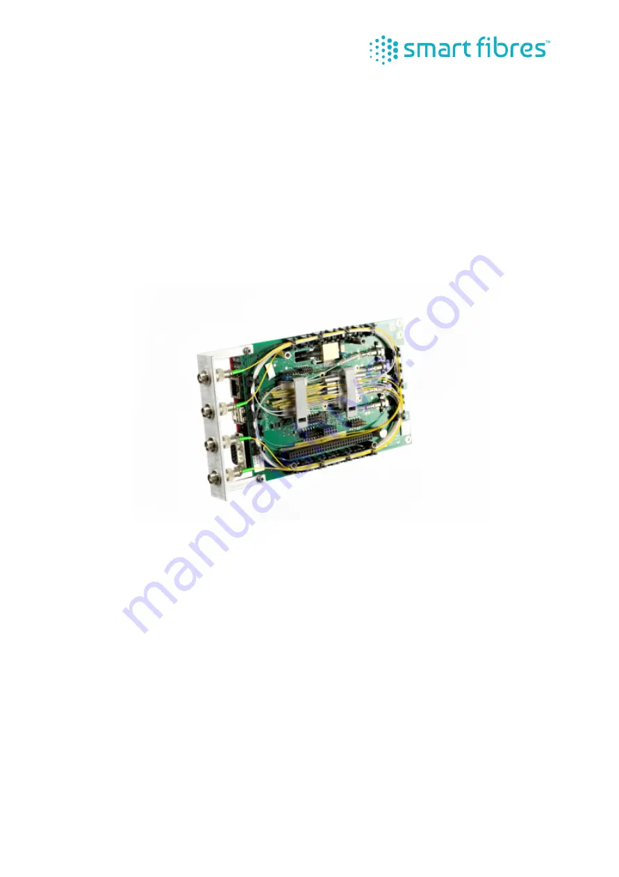
SmartScan SBI Interrogator
Product Manual
Page 1: ...D01816562 Rev A 30 04 2020 SmartScan SBI Interrogator Product Manual...
Page 2: ...for SmartScan Software Installation 9 Switching on the Interrogator 9 Switching off the Interrogator 9 Maintenance 9 Appendix A SmartSoft for SmartScan SBI User Manual 10 Installation 10 Preparing For...
Page 3: ...essively more development by the OEM Option 1 Purchase an SBI and TS 7200 Processing Module design your own housing and qualify to the relevant CE or equivalent regional standards for your market sect...
Page 4: ...I PM System Diagram Laser Laser Drive Detection Circuits Peak Processing PC 104 Interface High level processing Comms FBG1 FBG2 FBGn FBG1 FBG2 FBGn FBG1 FBG2 FBGn FBG1 FBG2 FBGn SBI PM RJ45 DC In 9 to...
Page 5: ...outputs for the interrogator are safe to view with the naked eye but should not be viewed through optical instruments such as microscopes and telescopes If viewing optical connector faces using optic...
Page 6: ...HM Minimum 0 2 nm 0 5 nm recommended Mechanical Environmental and Electrical Weight kg lbs 250g 0 55 lbs Dimensions H x D6 108 x 160 mm 4 25 x 6 3 Operating Temperature 20 to 65 C 4 to 149 F EMC Compl...
Page 7: ...minal for connecting 9 32 VDC power The Positive terminal is closest to the board corner The SBI generates all it s required voltages from this input and also outputs 5V on pins B3 and B29 of the PC10...
Page 8: ...ocessing Module The TS7200 SBC comes pre loaded with a Linux 2 6 36 kernel and root file system It is also preloaded with the libssi dynamic link library and a kernel driver module for the SBI which i...
Page 9: ...uld now be used to configure and acquire data from the interrogator Switching off the Interrogator The interrogator may be switched off by disconnecting the DC input voltage Maintenance The SmartScan...
Page 10: ...d its Net mask is 255 255 255 0 The Net mask for the PC must also be set to 255 255 255 0 suitable ranges for the PC s IP address are 10 0 0 1 to 10 0 0 149 or to 10 0 0 151 to 10 0 0 250 see Appendix...
Page 11: ...s stored settings Enhanced Acquisition is recommended for advanced users and is rich in features but requires more detailed settings Attempting to use enhanced mode without first reading this manual...
Page 12: ...hannel basis Automatic gain control ensures that the largest signal is not saturated If there are large differences in the signal intensity of FBGs on the same channel then per FBG gain can be used wi...
Page 13: ...ake place at regular intervals The file name will be appended with a date time string of the format YYYYMMDD HHMM_ where YYYY is the year MM is the month DD is the day HH is the hour of day and MM is...
Page 14: ...race To increase the displayed graph area one or both of the y axes can be hidden by pressing the appropriate or button Similarly the lower graph can be hidden using the V button between the two graph...
Page 15: ...limit depends on the maximum number of optical channels the instrument supports The user may configure the number of FBGs per channel Reducing the number of FBGs per channel enables the faster acquisi...
Page 16: ...transmitted It may be desirable to slow down the transmission rate because for example the data are transmitted over a slow network connection or because the host PC cannot process the data packets fa...
Page 17: ...0 8 nm from the end of the active laser range Do not set up more slots than the number of sensors per channel that was configured on the Acquisition Rate tab Slot boundaries can be adjusted by draggi...
Page 18: ...peak detection threshold may be adjusted for each channel on this tab Ensure the threshold level is above the background reflection level but not above any true FBG peaks In most cases a value of aro...
Page 19: ...irect connection to a host PC make sure to set the gateway address to match the network router or gateway PC s LAN address and that the SmartScan s IP address is unique on the network and not in the p...
Page 20: ...on for each system can be saved Instrument Setup Exiting Instrument Set Up There are three options for exiting Instrument Set Up pressing Save changes and exit will transfer all parameters to SmartSca...
Page 21: ...The graph palette in the top left corner of the graph provides options for navigating around the screen The cross icon is the selection tool and is used for selecting and moving graph cursors the magn...
Page 22: ...r channel setting If a gain slot is set up without an FBG reflection within it a sensor wavelength of zero is returned in the table The FBG table displays all the FBGs on channel 1 in descending wavel...
Page 23: ...sor dialog box Gratings page The reference wavelength is the wavelength against which the grating will be compared For some sensor types SmartSoft needs to measure a change in the wavelength of an FBG...
Page 24: ...available to choose from is determined by the sensor type selected The sensor selection page will not be available if the sensor type selected does not require it Press next to advance to the next di...
Page 25: ...s present in the Sensor table Sensors will be logged at the Data Processing Rate displayed at the top of the screen Set the target location and name of the log file by typing it in the box or by click...
Page 26: ...mat suitable for opening with common spreadsheet applications such as Microsoft Excel and OpenOffice Calc The Start Time is given in standard UTC format which is the number of seconds since 00 00 on 1...
Page 27: ...The chart can be expanded by hiding one of the y axes using the appropriate button The entire lower chart can also be hidden by pressing the long button whereby the upper chart expands to fill the wh...
Page 28: ...re located in the common application data directory e g C Documents and Settings All Users Application Data Smart Fibres SmartSoft SSI Graphics The location of the common application data folder is de...
Page 29: ...to a connected PC refer to Appendix C section Storage When replaying storage sessions it is not necessary to be connected to the interrogator Cancel the connection dialogue box and open the enhanced...
Page 30: ...at the highest speed the computer can handle At lower speeds time delays are introduced to enable data to be viewed on graphs or to prevent SmartSoft from monopolising the computer s processor Figure...
Page 31: ...m in to view a particular area of the frequency spectrum select the cross hair icon zoom out again The frequency scale on the x axis will be determined by the Acquisition frequency FFT theory dictates...
Page 32: ...o save settings Windows 10 Select Start then select Settings Network Internet For an Ethernet network select Ethernet then select the Ethernet network you re connected to Under IP assignment select Ed...
Page 33: ...features The final section describes how to transfer the storage files from the interrogator to a host PC where they may be played back or post processed http interface The existing interface is impl...
Page 34: ...erface network page The user may view and change the IP settings on this page Care should be taken to avoid losing track of the IP settings of the interrogator which might result in not being able to...
Page 35: ...find in the Set up screens of SmartSoft Although wavelength related settings are entered in units of Laser tuning steps these are integers usually with a value between 0 and 399 representing the wave...
Page 36: ...nd displayed in the form of an X Y graph The data that forms this graph is listed in table form Optical channels are number 0 to 3 rather than 1 to 4 Time Figure 34 http interface time page A page whe...
Page 37: ...tatus information and error codes should a problem occur The Update section allows the user to upgrade the embedded firmware using a script file that would be supplied by Smart Fibres Storage models w...
Page 38: ...take place and an error message No storage media or no space on mounted media will be reported on this page If the selected media device is full the user must delete storage sessions before further st...
Page 39: ...nterrogator has been switched on The session will end when storage is stopped via http or SmartSoft or when the storage device is full There could be one or many files in the session depending on the...
Page 40: ...ge files is to use the playback facility in SmartSoft see SmartSoft user guide for details File Transfer using WinSCP A facility for transferring storage files between interrogator and host PC has yet...
Page 41: ...requested leave it blank and continue You may see an error like Figure 40 WinSCP error message Just click OK You can prevent this in future by disabling lookup user groups in the advanced site setting...
Page 42: ...de navigate to VAR TMP SSI_STORAGE SSI The folder allows you to navigate up to the parent folder In the folder you should see any storage sessions listed with a ssf file extension Right click any file...
Page 43: ...user of a Smart Fibres product may not have all the correct equipment to hand but cleaning and inspection tools are relatively inexpensive and help to ensure continued correct operation of the interr...
Page 44: ...erial for each wipe Gentle but firm pressure is required enough to depress slightly the spring loaded ferrule We recommend you use a CLETOP S type cleaner for free connectors and a One Click type clea...
Page 45: ...No Yes 4th Dry Clean 5th Inspection 1st Wet Clean 5th Dry Clean 6th Inspection 2nd Wet Clean Make Connection Make Connection Make Connection Make Connection Clean No Yes Make Connection Clean No Yes...
Page 46: ...ector ferrule Contains a cassette of anti static cleaning cloth Pressing the blue lever exposes a fresh length of material The end face of the connector is then gently wiped across the exposed cloth i...
Page 47: ...e achieved by mounting the SBI in a similar type of enclosure The SBI and optional Processing Module are supplied as components for an OEM to integrate into their system therefore it is the responsibi...