background image

16

Centellis 2x00 User Card-10GE Installation and Use (6806800H33E)

Safety Notes

Safety Notes

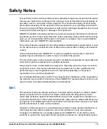
to show compliance with the above mentioned requirements. A proper installation in a
compliant system will maintain the required performance. Use only shielded cables when
connecting peripherals to assure that appropriate radio frequency emissions compliance is
maintained.

Installation

Before installing the board, make sure the requirements listed in section "Board Exchange"
are met.

Restricted access area - This board is only to be installed in a restricted access area.

Data Loss

Removing the board with the blue LED still blinking causes data loss.

Wait until the blue LED is permanently illuminated, before removing the board.

Damage of Circuits

Electrostatic discharge and incorrect board installation and removal can damage circuits or
shorten their life.

Before touching the board or electronic components, make sure that you are working in an
ESD-safe environment or wear ESD wrist straps.

Board Malfunctioning

Incorrect board installation and removal can result in board malfunctioning.

Make sure that the board is connected to the system backplane via all assembled
connectors and that power is available on all zone 1 power pins.

Damage of the Product

Incorrect installation of the product can cause damage of the product,

Only use handles when installing/removing the product to avoid damage/deformation to the
face plate and/or PCB.

Damage of the Product and Additional Devices and Modules

Incorrect installation or removal of additional devices or modules may damage the product
or the additional devices or modules.

Before installing or removing additional devices or modules, read the respective
documentation.

Summary of Contents for Centellis 2x00 User Card-10GE

Page 1: ...Centellis 2x00 User Card 10GE Installation and Use P N 6806800H33E January 2020 ...

Page 2: ...r to the products described therein at any time without notice SMART EC makes no commitment to update the information contained within these materials Electronic versions of this material may be read online downloaded for personal use or referenced in another document as a URL to a SMART EC website The text itself may not be published commercially in print or electronic form edited translated or o...

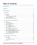
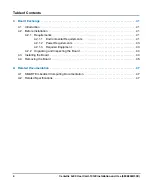
Page 3: ...rd 10GE Hardware 29 2 1 Overview 29 2 2 Payload Hardware 30 2 2 1 Ethernet Interfaces 30 2 3 IPMC Controller 30 2 3 1 IPMB0 Interface 30 2 3 2 IPMC Standard Functions 30 2 4 Power Supply 31 2 4 1 On board and External Supply 31 2 4 2 Power Supply Holdup 31 2 5 Installing and Removing SFP SFP Modules 32 2 5 1 Installing an SFP SFP Module 32 2 5 2 Removing an SFP SFP Module 34 2 6 Frame Ground and E...

Page 4: ...Installation 41 4 2 1 Requirements 41 4 2 1 1 Environmental Requirements 41 4 2 1 2 Power Requirements 43 4 2 1 3 Required Equipment 43 4 2 2 Unpacking and Inspecting the Board 44 4 3 Installing the Board 44 4 4 Removing the Board 45 A Related Documentation 47 A 1 SMART Embedded Computing Documentation 47 A 2 Related Specifications 47 ...

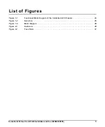
Page 5: ...is 2x00 User Card 10GE Installation and Use 6806800H33E 5 Figure 1 1 Functional Block Diagram of the Centellis 2x00 Chassis 24 Figure 1 2 Overview 25 Figure 1 3 Block Diagram 26 Figure 2 1 Hardware 29 Figure 3 1 Face Plate 37 ...

Page 6: ...List of Figures 6 Centellis 2x00 User Card 10GE Installation and Use 6806800H33E ...

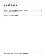
Page 7: ... 7 Table 1 1 Standard Compliances 27 Table 3 1 Face Plate LEDs 37 Table 3 2 Centellis 2x00 User Card 10GE Specific Sensors 38 Table 4 1 Environmental Requirements 42 Table 4 2 DC Board Power Requirements 43 Table A 1 SMART EC Documentation 47 Table A 2 Related Specifications 47 ...

Page 8: ...List of Tables 8 Centellis 2x00 User Card 10GE Installation and Use 6806800H33E ...

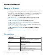
Page 9: ...s a German translation of the safety notes Chapter 1 Introduction on page 23 gives an overview of the product Chapter 2 Centellis 2x00 User Card 10GE Hardware on page 29 provides detailed hardware information of the product Chapter 3 Controls Indicators and Connectors on page 37 describes external interfaces of the product this includes connectors and LEDs Chapter 4 Board Exchange on page 41 descr...

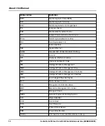
Page 10: ...enkter Haftung GND Ground HPI Hardware Platform Interface IEC International Electric Code IPM Intelligent Platform Management IPMB Intelligent Platform Management Bus IPMC Intelligent Platform Management Controller IPMI Intelligent Platform Management Interface LVDS Low Voltage Differential Signal MAC Media Access Control MIB Management Information Base MMC Mezzanine Management Controller MO Manag...

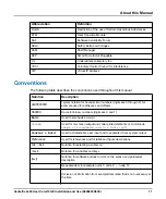
Page 11: ...l notation for hexadecimal numbers digits are 0 through F for example used for addresses and offsets 0b0000 Same for binary numbers digits are 0 and 1 bold Used to emphasize a word Screen Used for on screen output and code related elements or commands Sample of Programming used in a table 9pt Courier Bold Used to characterize user input and to separate it from system output Reference Used for refe...

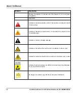
Page 12: ...erious injury Indicates a hazardous situation which if not avoided may result in minor or moderate injury Indicates a property damage message Indicates a hot surface that could result in moderate or serious injury Indicates an electrical situation that could result in moderate injury or death Indicates that when working in an ESD environment care should be taken to use proper ESD practices No dang...

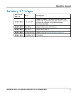
Page 13: ...ebrand to SMART Embedded Computing template Updated title Updated Centellis 2000 to Centellis 2x00 throughout the document Updated SMART EC Documentation table 6806800H33D May 2016 Removed Declaration of Conformity 6806800H33C May 2014 Rebranded to Artesyn 6806800H33B December 2012 Updated Standard Compliances on page 27 6806800H33A September 2010 First edition ...

Page 14: ...14 Centellis 2x00 User Card 10GE Installation and Use 6806800H33E About this Manual About this Manual ...

Page 15: ...nual is meant to complete the knowledge of a specialist and must not be used as replacement for qualified personnel Keep away from live circuits inside the equipment Operating personnel must not remove equipment covers Only factory authorized service personnel or other qualified service personnel may remove equipment covers for internal subassembly or component replacement or any internal adjustme...

Page 16: ...scharge and incorrect board installation and removal can damage circuits or shorten their life Before touching the board or electronic components make sure that you are working in an ESD safe environment or wear ESD wrist straps Board Malfunctioning Incorrect board installation and removal can result in board malfunctioning Make sure that the board is connected to the system backplane via all asse...

Page 17: ...amage or injuries always check that there is no more voltage on the line that has been disconnected before continuing your work Hot Swap Installing the board into or removing it from a powered system not supporting hot swap or high availability causes board damage and data loss Therefore only install it in or remove it from a powered system if the system itself supports hot swap or high availabili...

Page 18: ...18 Centellis 2x00 User Card 10GE Installation and Use 6806800H33E Safety Notes Safety Notes ...

Page 19: ...rf ausschließlich für Anwendungen in der Telekommunikationsindustrie und im Zusammenhang mit Industriesteuerungen verwendet werden Einbau Wartung und Betrieb dürfen nur von durch SMART EC ausgebildetem oder im Bereich Elektronik oder Elektrotechnik qualifiziertem Personal durchgeführt werden Die in diesem Handbuch enthaltenen Informationen dienen ausschließlich dazu das Wissen von Fachpersonal zu ...

Page 20: ...s von Zusatzmodulen So ist sichergestellt dass sich die Aussendung von Hochfrequenzstrahlung im Rahmen der erlaubten Grenzwerte bewegt Warnung Dies ist eine Einrichtung der Klasse A Diese Einrichtung kann im Wohnbereich Funkstörungen verursachen In diesem Fall kann vom Betreiber verlangt werden angemessene Maßnahmen durchzuführen Board Installation Bevor Sie das Board in einem System installieren ...

Page 21: ...s Hohe Luftfeuchtigkeit und Kondensat auf der Oberfläche des Boards können zu Kurzschlüssen führen Betreiben Sie das Board nur innerhalb der angegebenen Grenzwerte für die relative Luftfeuchtigkeit und Temperatur Stellen Sie vor dem Einschalten des Stroms sicher dass sich auf dem Board kein Kondensat befindet Überhitzung und Beschädigung des Boards Betreiben Sie das Board ohne Zwangsbelüftung kann...

Page 22: ...aubt Austausch Erweiterung Verwenden Sie bei Austausch oder Erweiterung nur von SMART EC empfohlene Komponenten und Systemteile Andernfalls sind Sie für mögliche Auswirkungen auf EMV oder Fehlfunktionen des Produktes voll verantwortlich Überprüfen Sie die gesamte aufgenomme Leistung aller eingebauten Komponenten siehe die technischen Daten der entsprechenden Komponente Stellen Sie sicher dass die ...

Page 23: ...corresponding AdvancedTCA blade The Centellis 2x00 User Card 10GE module is intended to be used in a Centellis 2x00 chassis The module when installed in the dedicated User Card slot provides uplink connectivity from the payload Ethernet fabric channel Figure 1 1 shows the functional block diagram of the Centellis 2x00 chassis including the two 10G User Cards in the lower part of the figure Each 10...

Page 24: ...24 Centellis 2x00 User Card 10GE Installation and Use 6806800H33E Introduction Introduction Figure 1 1 Functional Block Diagram of the Centellis 2x00 Chassis ...

Page 25: ...Introduction Centellis 2x00 User Card 10GE Installation and Use 6806800H33E 25 1 2 Hardware The following figure gives an overview about the main parts of the board Figure 1 2 Overview ...

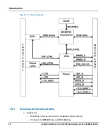
Page 26: ... 10GE Installation and Use 6806800H33E Introduction Introduction 1 2 1 Functional Characteristics Transceiver BCM8706 10GE Serial to XAUI 10GBASE LRM transceiver Compliant to IEEE 802 3ae and IEEE 802 3aq Figure 1 3 Block Diagram ...

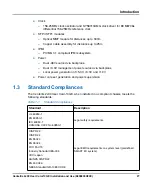
Page 27: ...ment power sourced via backplane Local power generation of 5 0V 3 3V and 1 0V Power on reset generation and power supervision 1 3 Standard Compliances The Centellis 2x00 User Card 10GE when installed in a compliant chassis meets the following standards Table 1 1 Standard Compliances Standard Description UL 60950 1 EN 60950 1 IEC 60950 1 CAN CSA C22 2 No 60950 1 Legal safety requirements CISPR 22 C...

Page 28: ...ontact your local SMART Embedded Computing sales representative or visit https www smartembedded com ec support ANSI IPC A610 Rev C Class 2 ANSI IPC 7711 ANSI IPC 7721 ANSI J 001 003 Manufacturing requirements NEBS Standard GR 63 CORE ETSI EN 300 019 series Environmental requirements PICMG 3 0 R3 0 Defines mechanics blade dimensions power distribution power and data connectors and system managemen...

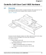
Page 29: ...ackplane connectors To prevent connector damage the alignment pin offers a guide rail to the slot and a coding mechanism to ensure the installation of the board in the matching slot The hardware consists of Payload hardware section with Ethernet interfaces to the backplane and to the face plate IPMI controller section with IPMB0 A and IPMB0 B interface to the backplane Handle switch and status LED...

Page 30: ... 3 IPMC Controller The IPMC Controller is derived from SMART EC s IPMC building block and it consists of two coupled micro controllers IPMC Master Controller IMC based on an Atmega 256 IPMC Slave Controller ISC based on an Atmega 168 2 3 1 IPMB0 Interface IPMB0 A is connected to the I2 C controller of the IMC IPMB0 B to the I2 C controller of the ISC Both micro controllers have their own I2 C cont...

Page 31: ...MI filter at the power input ensures conducted emission levels below EN 55022 class B 2 4 1 On board and External Supply The Centellis 2x00 User Card 10GE has no provisions to switch off the power input The board is powered whenever the power is attached to the Centellis 2x00 system 40VDC to 72VDC The board satisfies the standby power limit of 10W for AdvancedTCA FRUs Typical power consumption of ...

Page 32: ...nt safety standards may damage the RTM and the SFP SFP modules and may lead to personal injury Only use and install SFP SFP modules which are fully certified and which meet all relevant safety standards Personal Injury Optical SFP SFP modules may be classified as laser products When installing and using any of these SFP SFP modules the regulations which correspond to the respective laser class app...

Page 33: ... position 2 Remove the optical port plug NOTICE SFP SFP Module Damage The optical port plug protects the sensitive optical fibers against dirt and damage Dirt and damage can render the SFP SFP module inoperable Only remove the optical plug when you are ready to connect a cable to the SFP SFP module When no cable is connected cover the port with an optical port plug ...

Page 34: ...ellis 2x00 User Card 10GE Hardware Centellis 2x00 User Card 10GE Hardware 3 Connect the network cable to the SFP SFP module 2 5 2 Removing an SFP SFP Module Procedure In order to remove an SFP SFP module proceed as follows 1 Remove any connected cable from the SFP module ...

Page 35: ...d 10GE Installation and Use 6806800H33E 35 2 Open the SFP SFP latch Note that the latch mechanism of your SFP SFP module may be slightly different compared to the latch shown in the following figure 3 Grasp the SFP SFP module and carefully slide it out of the slot ...

Page 36: ...ace plate mounting holes of the board are connected to frame ground An ESD strip according to the AdvancedTCA specification PICMG 3 0 R3 0 is provided at one edge of the PCB NOTICE SFP SFP Module Damage The optical port plug protects the sensitive optical fibres against dirt and damage Dirt and damage can render the SFP SFP module inoperable Only remove the optical plug when you are ready to conne...

Page 37: ...Control via IPMI Programmer s Reference manual 3 1 2 Ethernet Connectors A SFP port located on the front panel allows for Ethernet connectivity from the payload to an external device Figure 3 1 Face Plate Table 3 1 Face Plate LEDs LED Color Description OOS failure Red Red The Centellis 2x00 User Card 10GE is out of service Off The Centellis 2x00 User Card 10GE is working properly OK power Green Gr...

Page 38: ...e sensor Sensor specific 6Fh IPMC_State OEM D5h IPMC state OEM sensor Sensor specific 6Fh IPMB0_State IPMB F1h IPMB0 state sensor Sensor specific 6Fh SFP_Enable Other FRU 1Ah Enable Disable SFP Writable OEM sensor No Type enable 9 SFP_TXDIS Other FRU 1Ah SFP TXDIS signal Yes Reading type failure 4 SFP_LOS Other FRU 1Ah Loss of signal indication Yes Reading type failure 4 SFP_TXFAULT Other FRU 1Ah ...

Page 39: ...nagement 3 3V sensor Yes Threshold 1 VOLTAGE_5_0 Voltage 02h 5 0V sensor Yes Threshold 1 TEMPERATURE0 Temperature 01h Temperature sensor 0 Yes Threshold 1 TEMPERATURE1 Temperature 01h Temperature sensor 2 Yes Threshold 1 SFP_TEMPERATURE Temperature 01h SFP Temperature sensor Yes Threshold 1 Table 3 2 Centellis 2x00 User Card 10GE Specific Sensors continued Sensor Name Sensor Type Code Description ...

Page 40: ...40 Centellis 2x00 User Card 10GE Installation and Use 6806800H33E Controls Indicators and Connectors Controls Indicators and Connectors ...

Page 41: ... and inspecting the board 4 2 1 Requirements Before you power up the board calculate the power needed according to your system configuration 4 2 1 1 Environmental Requirements You must make sure that the board when operated in your particular system configuration meets the environmental requirements specified below The system is shipped with pre installed Centellis 2x00 User Card 10GE boards You h...

Page 42: ...F exceptional operation according to NEBS Standard GR 63 CORE 40ºC 40 F to 85ºC 185 F Temp change 0 25ºC min according to NEBS Standard GR 63 CORE 0 25ºC min Relative humidity 5 to 90 non condensing according to SMART EC internal environmental requirements 5 to 95 non condensing according to SMART EC internal environmental requirements Vibration tested in target platform 0 1g from 5 to 100Hz and b...

Page 43: ... 0VDC 3 3VDC and 1 0VDC 5 0V voltage is generated from the 48V AdvancedTCA power by a DC DC converter with galvanic isolation suitable for TNV 2 circuits 3 3V and 1 0V voltages are derived from the 5 0V power The board provides two independent power inputs according to the AdvancedTCA specification Each input has to be equipped with an additional fuse of max 90A located either in the shelf where t...

Page 44: ...e Board Before starting to install the board observe the following NOTICE Board Damage Touching the board or electronic components in a non ESD protected environment causes component and board damage Before touching boards or electronic components make sure that you are working in an ESD safe environment or wear ESD wrist straps The board is thoroughly inspected before shipment If any damage occur...

Page 45: ...es until you feel resistance 5 Wait until the blue LED is illuminated 6 Tighten the screws on the left and on the right of the board In this way the handle switch activator is closed and the board can be powered The blue LED blinks 7 Wait until the blue LED is switched off The switched off blue LED indicates that the board is activated 8 Attach cables to the front panel connectors as necessary 4 4...

Page 46: ...fasten the screws of the face plate until the handle is detached from the front panel of the board The handle switch activator triggers the blinking of the blue LED The hotswap state remains in the state extraction pending so that the blue LED is still blinking 6 Wait until the blue LED is illuminated 7 Remove the board from the shelf using the extraction handles ...

Page 47: ...s subject to change without notice Table A 1 SMART EC Documentation Document Title Publication Number Centellis 2100 Data Sheet Centellis 2100 DS Centellis 2000 Data Sheet Centellis 2000 DS Centellis 2000 DC Release 1 2 Installation and Use 6806800J13 Centellis 2000 AC Installation and Use 6806800J87 Centellis 2x00 User Card 10GE Control via IPMI Programmer s Reference 6806800K89 System Management...

Page 48: ...48 Centellis 2x00 User Card 10GE Installation and Use 6806800H33E Related Documentation ...

Page 49: ...1 ...

Page 50: ...registered trademark of SMART Modular Technologies Inc and SMART Embedded Computing and the SMART Embedded Computing logo are trademarks of SMART Modular Technologies Inc All other names and logos referred to are trade names trademarks or registered trademarks of their respective owners ...

Reviews: