background image

10 Compliance Information

FCC Compliance

This device complies with Part 15 of the FCC Rules. Operation is subject to the following conditions:

1. This device may not cause harmful interference, and
2. This device must accept any interference received, including interference that may cause

undesired operation.

NOTE: This equipment has been tested and found to comply with the limits for a Class B digital
device, pursuant to Part 15 of the FCC Rules. These limits are designed to provide reasonable
protection against harmful interference in a residential installation. This equipment generates, uses,
and can radiate radio frequency energy and if not installed and used in accordance with the
instructions, may cause harmful interference to radio communications. However, there is no
guarantee that interference will not occur in a particular installation. If this equipment does cause
harmful interference to radio or television reception, which can be determined by turning the
equipment off and on, the user is encouraged to try to correct the interference by one or more of
the following measures:

• Reorient or relocate the receiving antenna.
• Increase the separation between the equipment and the receiver.
• Connect the equipment into an outlet on a circuit different from that to which the receiver is

connected.

• Consult the dealer or an experienced radio/TV technician for help.

The user is cautioned that changes or modifications not expressly approved by SMA Solar
Technology America LLC could void the user’s authority to operate this equipment.

IC Compliance

This Class B digital apparatus complies with Canadian ICES-003.
Cet appareil numérique de la classe B est conforme à la norme NMB-003 du Canada.

10 Compliance Information

SMA Solar Technology America LLC

User Manual

SB5.0-6.0-1SP-US-40-BA-en-10

62

Summary of Contents for SB 5.0-1SP-US-40

Page 1: ...User Manual SUNNY BOY 5 0 6 0 SB5 0 6 0 1SP US 40 BA en 10 Version 1 0 ENGLISH...

Page 2: ...however that product improvements and field usage experience may cause SMA Solar Technology America LLC and or SMA Solar Technology Canada Inc to make changes to these specifications without advance n...

Page 3: ...or other equipment connected to the SMA equipment or personal injury Symbol Description DANGER indicates a hazardous situation which if not avoided will result in death or serious injury WARNING indi...

Page 4: ...h the laws regulations codes and standards applicable in the jurisdiction of installation SMA assumes no responsibility for the compliance or non compliance with such laws or codes in connection with...

Page 5: ...3 1 Activating Secure Power Supply Operation 17 4 3 2 Deactivating Secure Power Supply Operation 18 5 Using the Inverter User Interface 19 5 1 Establishing a connection to the user interface 19 5 1 1...

Page 6: ...Adopting a Configuration from a File 33 6 9 Switching the Dynamic Power Display Off 33 6 10 Switching WLAN On and Off 34 7 Cleaning the Inverter 35 8 Troubleshooting 36 8 1 Forgotten Password 36 8 2...

Page 7: ...g in the installation and commissioning of electrical devices and installations Knowledge of the applicable standards and directives Knowledge of and compliance with this document and all safety infor...

Page 8: ...chnical Information 1 5 Nomenclature Complete designation Designation in this document Sunny Boy Inverter product SMA Solar Technology America LLC SMA SMA Solar Technology Canada Inc 1 6 Typographies...

Page 9: ...st excessive reverse currents under fault conditions the National Electrical Code Section 690 9 requires overcurrent protection for PV source circuits where possible short circuit currents exceed the...

Page 10: ...rface of the inverter can get very hot Touching the surface can result in burns Mount the inverter in such a way that it cannot be touched inadvertently Do not touch hot surfaces Wait 30 minutes for t...

Page 11: ...nit B Enclosure lid of the Power Unit C Enclosure lid for the Connection Unit D Connection Unit E DC load break switch The inverter is equipped with a DC load break switch If the DC load break switch...

Page 12: ...egistration in Sunny Portal Registration ID RID for registration in Sunny Portal WLAN password WPA2 PSK for the direct connection to the user interface of the inverter via WLAN H Display The display s...

Page 13: ...verter The inverter user interface can be called up via the web browser if there is an existing WLAN or Ethernet connection to a computer tablet PC or smartphone Speedwire Webconnect The inverter is e...

Page 14: ...ion function allows the DC inputs A and B of the inverter to operate in parallel and up to three strings to be connected to it in parallel As a result as opposed to normal operation up to four strings...

Page 15: ...standard The multifunction relay is a multifunctional interface that can be configured for the operating mode used by a particular system Arc Fault Circuit Interrupter AFCI In accordance with the Nati...

Page 16: ...via the green LED The green LED pulses faster or slower de pending on the power If necessary you can switch off the dynamic power display via the green LED Red LED glowing Event occurred In addition...

Page 17: ...power supply operation In case of overload underload or insufficient solar irradiation the voltage supply of the outlet is briefly interrupted The inverter automatically attempts to reestablish the v...

Page 18: ...on the control light of the outlet for secure power supply operation glows The green LED does not flash and no message that the secure power supply operation mode is activated appears on the display o...

Page 19: ...operating hours SMA 12345 Device specific WLAN password usable for initial configuration to completion of the first ten operating hours see WPA2 PSK on the type label of the inverter Standard IP inve...

Page 20: ...e loading the user interface The login page of the user interface opens 5 Log into the user interface see Section 5 2 page 22 5 1 2 Establishing a Direct Connection via Ethernet Requirements The inver...

Page 21: ...ill be assigned automatically by the DHCP server router or manually by you Upon completion of the configuration the inverter is only reachable via this new IP address or the alternative addresses Acce...

Page 22: ...IP address has been confirmed by pressing the enter key a message might appear indicating that the connection to the user interface of the inverter is not secure SMA guarantees that calling up the use...

Page 23: ...er 1 In the drop down list Language select the desired language 2 In the User group drop down list select the entry Installer or User 3 Enter the password in the field Password 4 Select Login The star...

Page 24: ...Page Design of the User Interface A B C E F D Figure 2 Start Page Design of the User Interface 5 Using the Inverter User Interface SMA Solar Technology America LLC User Manual SB5 0 6 0 1SP US 40 BA...

Page 25: ...ll be displayed System Configuration The following settings for the inverter can be performed here The selection available is dependent on which user group you are logged in as and the operating syste...

Page 26: ...ce status Displays whether the inverter is currently in a fault free operating state or whether there is an event type Error or Warning present Current power Displays the power currently being generat...

Page 27: ...e installation assistant steps The number of steps depends on the type of device and the additionally installed modules The current step is highlighted in blue B User information Information about the...

Page 28: ...word in the communication product the inverter can no longer be reached by the communication product Ensure that the password for the user group Installer is the same as the system password in the com...

Page 29: ...ity for missing or incorrect data and possibly resulting yield losses Use the user interface for the configuration of the inverter Requirements The changes to the grid relevant parameters must be appr...

Page 30: ...a 208 V wye connection or a 240 V split phase system and the associated country data set UL1741 2010 120 is factory set If the default country data set does not correspond with the grid configuration...

Page 31: ...esired value This will configure the minimum time for which the power must have exceeded the minimum switch on power threshold in order to trip activation of the load Select the parameter Minimum On t...

Page 32: ...se In order to deactivate the Modbus interface reset the inverter to default settings Procedure Activate the Modbus interface and adjust the communication ports if necessary see the Technical Descript...

Page 33: ...ust be available see Application for SMA Grid Guard Code at www SMA Solar com Changes to grid relevant parameters must be approved by the responsible grid operator Procedure 1 Activate the user interf...

Page 34: ...rocedure To switch off the direct connection select the parameter Soft access point is turned on and set this to No To switch off the connection in the local network select the parameter WLAN is turne...

Page 35: ...the inverter is dirty clean the enclosure the enclosure lid of the Connection Unit the enclosure lid of the Power Unit the type label the display and the LEDs with a damp cloth and clear water only 7...

Page 36: ...19 3 Enter the PUK instead of the password into the field Password 4 Call up the menu Device Parameters 5 Select Edit parameters 6 In the parameter group User Rights Access Control change the password...

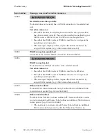
Page 37: ...act page 63 202 to 206 Grid fault The utility grid has been disconnected the AC cable is damaged or the grid voltage at the connection point of the inverter is too low The inverter has dis connected f...

Page 38: ...occur If fluctuations occur frequently and this message is displayed often contact the grid operator and request approval to change the operating parameters of the inverter If the grid operator gives...

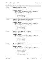
Page 39: ...d Corrective measures Ensure that L and N are correctly connected see installation manual 1302 Waiting for grid voltage Installation failure grid connection Check grid and fuses L or N not connected C...

Page 40: ...voltage sources immediately see installation manual Check whether the DC voltage is below the maximum input voltage of the inverter If the DC voltage is below the maximum input voltage of the inverte...

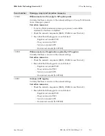
Page 41: ...tion 8 3 page 55 3801 DC overcurrent Check generator Overcurrent at the DC input The inverter briefly interrupts feed in operation Corrective measures If this message is displayed frequently ensure th...

Page 42: ...s If this message is displayed frequently contact the Service see Section 11 Contact page 63 6803 Self diagnosis Input A defective The cause must be determined by the Service Corrective measures Conta...

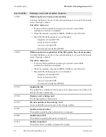
Page 43: ...date transport started Update file is being copied 7332 Update transport successful Update file was copied successfully to the inverter s internal memory 7333 Update transport failed Update file could...

Page 44: ...has started The configuration file is being transferred 7351 Update WLAN The inverter is updating the WLAN module 7352 Update of WLAN not successful The update of the WLAN module failed Corrective me...

Page 45: ...ame network as the inverter see energy meter manual For WLAN connection improve the WLAN connection quality e g via SMA Antenna Extension Kit or connect the inverter with the DHCP server router via Et...

Page 46: ...ol absent Depending on the fall back set ting either the last received values will be retained or the active power will be limited to the set percentage value of the inverter nominal power Corrective...

Page 47: ...slots and make any necessary corrections 9203 Short circuit in the SPS power outlet The maximum initial load has been overshot or the appliance s initial current is above the maximum permissible load...

Page 48: ...Ethernet connection the network cable and the network connector are not damaged and that the network connectors are correctly plugged If necessary increase the data query intervals If necessary reduce...

Page 49: ...of the network connector Corrective measures if the status is Half Ensure that with an Ethernet connection the network cable and the network connector are not damaged and that the network connectors...

Page 50: ...s lost WLAN connection to the selected network Corrective measures Ensure that the WLAN router or WLAN Access Point is still active Ensure that the WLAN router or WLAN Access Point is in range and is...

Page 51: ...a de 9523 Proxy ied sma de 9523 Stun stun sma de 3478 Domain ied sma de for SIP URI 10344 Webconnect error DNS server not configured It is likely that there is an error in the network settings Correct...

Page 52: ...tings Corrective measures Check the network components DLAN WLAN Access Point etc Ensure that the following ports are not blocked Registrar ied sma de 9523 Proxy ied sma de 9523 Stun stun sma de 3478...

Page 53: ...onnect error Registration rejected by SIP registrar It is likely that there is an error in the network settings Corrective measures Check the network components DLAN WLAN Access Point etc Ensure that...

Page 54: ...measures If a Sunny Portal maintenance message is present wait until the maintenance has been completed Check the network components DLAN WLAN Access Point etc Ensure that the following ports are not...

Page 55: ...to life due to electric shock In the event of a ground fault high voltages can be present Touch the cables of the PV array on the insulation only Do not touch any parts of the substructure or frame of...

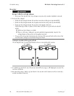
Page 56: ...f the two voltages to ground potential is approximately equal to the voltage between the positive and negative terminals If a ground fault is present determine the location of the ground fault via the...

Page 57: ...for further information on calculating the insulation resistance see the Technical Information Insulation Resistance Riso of Non Galvanically Isolated PV Systems at www SMA Solar com Required devices...

Page 58: ...ble for the inverter in the present quantity 8 4 Resetting the Operation Inhibition after Detection of an Arc Fault If the red LED is glowing and the event number 4301 is shown on the display and or i...

Page 59: ...he user interface see Section 5 1 page 19 5 Log into the user interface as an Installer see Section 5 2 page 22 6 Reset the operation inhibition by setting one of the following parameters Select the p...

Page 60: ...flash drive in the USB port on the communication assembly 5 Commission the inverter see inverter installation manual During start up phase of the inverter the desired firmware is being installed At t...

Page 61: ...Multi function interface for one SMA in verter as retrofit kit for capturing environ mental data e g irradiation ambient tem perature cell temperature wind speed or S0 meters MD SEN US 40 SMA Antenna...

Page 62: ...nce will not occur in a particular installation If this equipment does cause harmful interference to radio or television reception which can be determined by turning the equipment off and on the user...

Page 63: ...pment e g communication products If necessary system name in the Sunny Portal If necessary access data in the Sunny Portal Operating mode of the multifunction relay United States Esta dos Unidos SMA S...

Page 64: ...www SMA Solar com...

Reviews: