4. Connect the measuring device for insulation resistance.
5. Short-circuit the first string.
6. Set the test voltage. The test voltage should be as close as possible to the maximum system
voltage of the PV modules but must not exceed it (see datasheet of the PV modules).
7. Measure the insulation resistance.
8. Eliminate the short circuit.
9. Measure the remaining strings in the same manner.
☑ If the insulation resistance of a string deviates considerably from the theoretically
calculated value, there is a ground fault present in that string.
10. Reconnect to the inverter only those strings from which the ground fault has been eliminated.
11. Reconnect all other strings to the inverter.
12. Recommission the inverter (see inverter installation manual).
13. If the inverter still displays an insulation error, contact the Service (see Section 11 "Contact",
page 63). The PV modules might not be suitable for the inverter in the present quantity.
8.4
Resetting the Operation Inhibition after Detection of an
Arc Fault
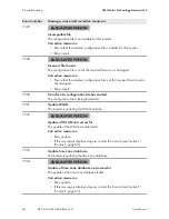
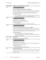
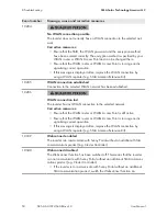
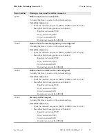
If the red LED is glowing and the event number
4301
is shown on the display and/or in the event
list on the user interface of the inverter, the inverter has detected an electric arc and interrupts feed-
in operation.
There are two options for resetting the operation inhibition:
• Reset the operation inhibition by tapping twice on the enclosure lid of the Connection Unit.
• Reset the operation inhibition by parameter setting.
Reset the operation inhibition by tapping twice on the enclosure lid of the
Connection Unit
1.
Danger to life due to electric shock
• Disconnect the inverter from any voltage sources (see the inverter installation manual).
2. Ensure that the PV modules, the connected DC cables and the connecting terminal plate for the
DC connection are not defective.
Repair or replace defective PV modules, DC cables or connecting terminal plate for the DC
connection.
8 Troubleshooting
SMA Solar Technology America LLC
User Manual
SB5.0-6.0-1SP-US-40-BA-en-10
58

