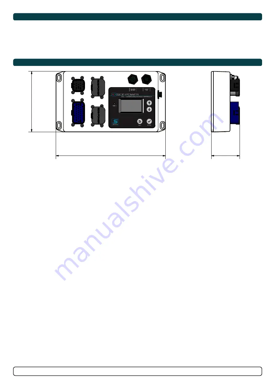
Sleipner PHC-3 User Manual Download Page 24

24

5267

15

2022

-

PHC-3

Technical Specifi cations and Measurements

Measurements

MC_0200

MC_0200

1

1

2

2

3

3

4

4

5

5

6

6

7

7

8

8

A

A

B

B

C

C

D

D

E

E

F

F


11/13/2017

1

Designed by

Date

1 / 1 

Edition

Sheet

olekr

 Material Type

Drawing nr

SM-122271

Copyright All rights reserved

Part nr

Size

Scale

Title


Tolerance

NS-ISO 2768-1


SLEIPNER MOTOR AS

A2

0.302 kg


Weight


12

0

217

56

Supply Voltage                        9-31 VDC

Power consumption            

Less than 1.0 Watt in stand-by

Digital output 1 to 6               Max load 2.0 Amp pr. output

Digital inputs                           0-31 VDC

Operating temperature       

-20°C to 70°C (-4°F to 158°F)

Weight                                    

700g/24,7oz

IP rating                                  

IP65

MC_0120

S-Link System Description

S-Link is a CAN-based control system used for communication between Sleipner products installed on a vessel. The system uses BACKBONE Cables 

as a common power and communication bus with separate SPUR Cables to each connected unit. Units with low power consumption are powered 

directly from the S-Link bus therefore one power cable must be connected to the BACKBONE Cable through a T-Connector. The S-Link cables should 

be installed such that sharp bend radius is avoided. Locking mechanism of connectors must be fully closed. Cables, T-Connectors and Extenders 

should not be located such that they are permanently immersed in water or other fluids. 


Main advantages of S-Link system:

-    Compact and waterproof plugs.

-    BACKBONE and SPUR Cables have different colour coding and keying to ensure correct and easy installation. BACKBONE Cables have blue  

  connectors and SPUR Cables have green connectors.

-    Different cable lengths and BACKBONE Extenders makes the system scalable and flexible to install. 

Installation of S-Link cables:

Select appropriate cables to keep the length of BACKBONE- and SPUR Cables to a minimum. In case of planned installation with total BACKBONE 

Cable length exceeding 100 meters please consult your local distributor. The S-Link cables should be installed to ensure sharp bend radius’s is 

avoided. The locking mechanism on connectors must be fully closed. To ensure long lifetime, cables, T-Connectors and Extenders should not be 

located so that they are permanently immersed in water or other fluids. It is also recommended to install cables such that water and condensation do 

not run along the cables and into the connectors.

The POWER Cable should ideally be connected around the middle of the BACKBONE Cable to ensure an equal voltage drop at each end of the 

BACKBONE Cable. The yellow and black wire in the POWER Cable shall be connected to GND and the red wire connected to +12VDC or +24VDC.

To reduce the risk of interference, avoid routing the S-Link cables close to equipment such as radio transmitters, antennas or high voltage cables. The 

backbone must be terminated at each end with the END Terminator.

SPUR cables can be left unterminated to prepare for the installation of future additional equipment. In such cases, ensure to protect open connectors 

from water and moisture to avoid corrosion in the connectors.

MG_0159

BACKBONE Cable

Forms the communication and power bus throughout 

a vessel. Available in different standard lengths.

*Blue ends

*Blue ends

*Blue ends

*Blue ends

*Blue ends

*Blue ends

*Blue ends

*Blue ends

*Blue ends

*Green ends

*Green ends

*Green ends

*Green ends

*Green ends

SPUR Cable

Used to connect S-Link compliant products to the 

backbone cable. One SPUR Cable must be used for 

each connected component, with no exceptions. 

Recommended to be as short as practically possible. 

Available in different standard lengths.

POWER Cable

Required in all installations for connection of BACKBONE 

Cable to a power supply. It shall not be more than one 

POWER Cable in an installation.

4-Port T-Connector

The 4-PORT T-connector allows multiple SPUR Cables to be 

connected. The 4-PORT T-connector comes with two sealing 

caps to protect unused ports.

T-Connector

Used for connection of SPUR 

or POWER Cable to the 

BACKBONE Cable. One 

T-Connector for each 

connected cable.

BACKBONE Extender

Connects two BACKBONE 

Cables to extend the length. 

END Terminator

Must be one at each end of 

the BACKBONE bus. 

+12/24V

GND

Optional 

ON/OFF Switch

 Fuse 2A

S-Link installation example

Spur

Power

T-Connector

End 

Terminator

End 

Terminator

Backbone Extender

Bow Thruster

Control Panel

Backbone

Backbone

Backbone

Spur

*For DC system

Spur

4 Port T-Connector

4 Port T-Connector

Stern Thruster

Automatic 

Main switch

S-Link

Power 

Supply

yellow

red

black

Summary of Contents for PHC-3

Page 1: ...d Norway www sleipnergroup com DOCUMENT ID REVISION DATE LANGUAGE To download your language go to www sleipnergroup com Including Installation For Hydraulic Proportional Controller PHC 3 5267 15 K e e...

Page 2: ...Menu Parameters 6 12 Menu Diagnostic 13 16 Menu Operation 17 18 PHC 3 Alarm Descriptions 19 21 Installation Manual Responsibility of the Installer 22 Considerations and Precautions for S Link Systems...

Page 3: ...display and button interface allow for local con guration of parameters and info LED Status Hydraulic cooling pump output Stabilizer hydraulics connections dump unload PTO main valve Power 24V Power...

Page 4: ...or run enable signal from power management system OIL TEMP Oil temp and oil level screen will not show if tank monitor sensor type parameter 0201 is deactivated Tank monitor sensor type set to analogu...

Page 5: ...ive Faults Menu Device INFO MC_0201 MC_0201 FAULTS flashing in upper left corner when any fault has been triggered Go to ACTIVE FAULTS menu for fault details Menu Active Faults Menu Device INFO Device...

Page 6: ...ad sharing between two PTO pumps by shutting down the second PTO pump PUMP2 OUTPUT when not needed two PTO pumps control valves required to reduce heat generation in the system and save fuel energy Wh...

Page 7: ...nalog temp sensor NTC 10K part no 10 2543 0202 OIL ALARM LEVEL Sets the oil alarm level 0 100 default 65 Alarm level in steps of 5 0203 TANK HEIGHT The height of the oil tank If tank don t have flat b...

Page 8: ...PUMP TYPE 800rpm 1600rpm default 1400rpm Speed in steps of 100rpm 0304 POWER SAVE Cooling pump power save function DEACTIVATED POWER SAVE is deactivated and cooling pump will act accordingly to PUMP M...

Page 9: ...ning 5 5 STERN THRUST ACTIVE Output is activated when stern thruster is running 6 6 ANY THRUST ACTIVE Output is activated when bow or stern thruster is running 7 7 THRUSTER ENABLED Output is activated...

Page 10: ...nputs is active and all inputs must be deactivated to deactivate the function 0 NOT IN USE default Digital input is not in use and deactivated 1 1 START POWERPACK When the input is activated the AC po...

Page 11: ...steps of 1 1009 PTO PUMP PRESSURE DETECT LEVEL De nes detection level for PTO standby pressure if parameter 0104 SYSTEM PRESSURE is set to ANALOG INPUT Pressure above level indicates that main engine...

Page 12: ...he BOW valve output direction for all parameter 0102 THRUSTER CONFIG settings NORMAL default Normal thruster direction SWAPPED Swapped thruster direction 2003 MAX SPOOL TRAVEL Scaling of valves spool...

Page 13: ...00ms default 200ms In steps of 100ms 2105 RAMP DECREASE De nes the time the output signal uses to go from 100 to 0 100ms 10000ms default 200ms In steps of 100ms 2106 DIRECTION LOCK De nes the time fro...

Page 14: ...Pressure 4 Set MAX SPOOL TRAVEL parameter 2003 to what Output in shows at maximum thrust and maximum Sys Pressure Shows live update of inputs and outputs related to stern thruster function In Display...

Page 15: ...0 Volt 1 output is energized When an output is highlighted the output will be toggled as long as the Enter button is being pushed and held In Display Description LS Dump LS Dump Valve Pump 2 Shutdown...

Page 16: ...A 0bar STAB PRESSURE Stabilizer Pressure in mA 4 0mA 0bar Shows live update of digital inputs 0 input is shorted to 0 Volt activated 1 input is open deactivated Scroll down to view more inputs In Disp...

Page 17: ...during reception increments the value After every successful reception the value is decremented Tx Error Count Transmit error counter Error during transmit increments the value After every successful...

Page 18: ...is displayed While VFD is running it is possible to press Back and go to parameters and change parameter values like 1003 PRESSURE SETPOINT or view DIGITAL OUTPUTS Waiting for power management system...

Page 19: ...DC current 3 1A ECI cooling pump motor peak current 12 4A Hydraulic cooling pump is selected in parameter 0301 and is ready to be operated The following data is shown in this example Hydraulic oil tem...

Page 20: ...ircuit System pressure sensor open circuit Sensor not connected or wire break Verify system pressure parameter 0104 10503 0 16 PHC System Pressure Short Circuit System pressure sensor short circuit Wi...

Page 21: ...ECI cooling pump overvoltage voltage higher than 33 0V Check PHC 3 input voltage is below 33 0V Replace ECI cooling pump 10524 0 54 PHC ECI Cooling Pump Undervoltage ECI cooling pump under voltage vo...

Page 22: ...MC_0105 The installer must read this document to ensure necessary familiarity with the product before installation Instructions in this document cannot be guaranteed to comply with all international a...

Page 23: ...system and attach using 4 M5x16 screws 2 Attach the required cables to the PHC 3 MC_0431 MG_0485 1 2 Tank sensor cable Black X3 S Link cable X5 Power colling pump cable Blue X1 Hydraulic colling pump...

Page 24: ...esigned by olekr Copyright All rights reserved SLEIPNER MOTO 120 217 56 Supply Voltage 9 31 VDC Power consumption Less than 1 0 Watt in stand by Digital output 1 to 6 Max load 2 0 Amp pr output Digita...

Page 25: ...eally be connected around the middle of the BACKBONE Cable to ensure an equal voltage drop at each end of the BACKBONE Cable The yellow and black wire in the POWER Cable shall be connected to GND and...

Page 26: ...STB SCU GW 1 Panel TP 43A S link Encoder Encoder 1 4 2 SCU Power Supply cable 3 Encoder cable 5 Encoder cable 5 FCU Harness 6 FCU Harness 6 SCU FCU cable 7 SCU FCU cable 7 VFD BUS cable 8 Pump Power...

Page 27: ...C 3 X1 Harness Part 151470 1 10 Pump power cable Part 10 2371 24v Pump power cable Part 10 2357 hyd MC_0218 IMPORTANT If installing S link products DO NOT connect any other control equipment to the S...

Page 28: ...rial number ie Thruster AMS PPC etc Bow Bow STB Stern Stern STB Fill in the type location and serial numbers of the S link devices installed Keeping this as a reference will make the setup procedure e...

Page 29: ...to the Purchaser at the Warrantor s expense If on the other hand the claim is determined to result from circumstances such as described in section 4 above or a result of wear and tear exceeding that...

Page 30: ...30 5267 15 2022 PHC 3 MC_0037 Notes...

Page 31: ...31 5267 15 2022 PHC 3 MC_0037 Notes...

Page 32: ...accuracies or omissions it may contain Continuous product improvement may change the product speci cations without notice Therefore Sleipner Group cannot accept liability for any possible differences...

Reviews: