11
®
STEP 7: INSTALL POWER AND THERMOSTAT WIRING
LO
HI
FT1 FT2 T1 T2
A1 A2
A
U
T
O
/M
A
N
C
A
L
/O
P
L
O
/H
I
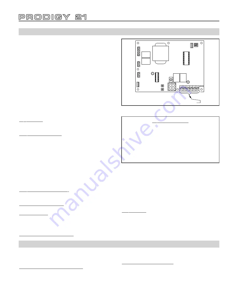
Thermostat & Alarm Terminals
Figure 16: Electronic Boiler Control Board
DANGER: BEFORE WIRING, ALWAYS TURN OFF
ELECTRIC POWER SUPPLY. OTHERWISE, SHOCK
OR DEATH CAN RESULT.
WARNING: DO NOT USE BOILER TRANSFORMER
TO POWER EXTERNAL ACCESSORIES (i.e. ZONE
VALVES, RELAYS). OVERLOADED/BURNED-OUT
TRANSFORMER CAN RESULT.
WARNING: DO NOT CONNECT WIRES CARRYING
POWER FROM AN EXTERNAL SOURCE TO THER-
MOSTAT OR AQUASTAT TERMINALS. SEVERE DAM-
AGE TO THE CONTROL BOARD CAN OCCUR.
Boiler must be electrically grounded in accordance with
the requirements of the authority having jurisdiction or,
in the absence of such requirements, with the National
Electrical Code, ANSI/NFPA 70.
Power Supply: A separately fused circuit is recommend-
ed. Use a standard 15-amp fuse or breaker and 14-
gauge conductors in BX cable or conduit.
Thermostat Connections: The boiler will run at high or
low fire, depending on space heating needs, when the
T1 and T2 terminals are closed. Connect low voltage
wiring from space heating zones to T1 and T2 terminals
on control board. Wire connections to T1 and T2 termi-
nal block must be from an isolated circuit. DO NOT
BRING VOLTAGE FROM AN EXTERNAL SOURCE
HERE. Wires should be only run from thermostats, zone
valve end switches, or circulator end switches. 3 wire
zone valves which do not have isolated end switches
cannot be used unless a relay is added with the dry
contacts wired to T1 and T2.
Thermostat Heat Anticipator: For zoned system, set to
match amp draw of zone valve or circulator relay. For a
non-zoned system, set to .3 amps.
Circulator Relay on Board: DO NOT exceed 5
amp/120V max. rating.
Wiring Diagrams: See index on Page 20 for zoning with
zone valves, indirect-fired water heater and reference
boiler diagram.
OPTIONS AVAILABLE
Domestic Hot Water Installation: The boiler will run at
high fire mode for maximum recovery of the Storage
Tank when the A1 and A2 terminals are closed.
Connect zone valve end switch to A1 and A2 terminals
on electronic boiler control board. Water heater thermo-
stat operates zone valve. DO NOT bring power from an
external source to these terminals. Note: 3 wire zone
valves which do not have isolated end switches cannot
be used unless a relay is added with the dry contacts
wired to T1 and T2.
Alarm System: A remote-type alarm device may be con-
nected to the boiler that will be activated if the boiler
shuts down due to a malfunction. FT1 and FT2 termi-
nals on electronic boiler control board are a dry contact
(5 amp 120 V max) that makes on a system fault or
power outage.
STEP 8: INSTALL JACKET ENCLOSURE
Power Connections
• Remove electrical junction box cover.
• HOT CONNECTION LEAD IS BLACK.
• NEUTRAL CONNECTION LEAD IS WHITE.
• Connect ground inside box.
DO NOT REVERSE POWER CONNECTIONS; if
reversed, ignition control will not detect a flame and
will go into safety shutdown.
The jacket can also be installed after start-up proce-
dures. Jacket components include boiler enclosure and
front cover.
TO INSTALL BOILER ENCLOSURE
• For side wall venting ONLY, remove appropriate vent
side panel from enclosure (located at top of sides).
• Place enclosure top over top flange of wall panel.
• Slide down until slots (on the insides of enclosure) are
seated in support brackets on mounting panel.
• Attach sheet metal enclosure to wall panel on both
sides with screws.
TO INSTALL FRONT COVER
• Insert the slots in cover bottom over support clips on
sheet metal enclosure bottom.
• Line up temperature/pressure indicator and push
cover in until support clip (at enclosure top) snaps
into slot on cover top.
• Install the 4 LED window plugs into the front cover
holes (if not factory installed).
Summary of Contents for Prodigy 21 KC-45
Page 22: ...22...


