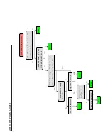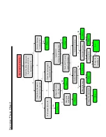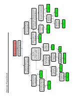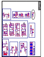
Y
Y
Y
Y
Y
OK
OK
OK
OK
OK
OK
N
N
N
N
N
N
N
N
N
N
N
Has audio but no video
Check
if
the
backlight
is
on
Done
Check
the
connector
of
b
ackli
g
ht
inve
rter
connected
Check
the
L
VDS
line
if
it
is
connected
Safely
connect
the
inverter
line
Check
the
voltage
of
inverter
line is
24V
Done
Y
Y
Y
N
N
N
Check
the
“ON/OFF”
voltage
on
“CN7”,
sh
ould
be
greater
than
2.7V
Check
“Q39”
&
“U9”
PinAB24
if
it
works
well.
Change
the
panel.
Done
Upgrade
the
software
Change
the
“Q
39”
or
“U9”
Change
the
“U9”
Done
Done
Done
Upgrade
the
software
Done
Safely
connect
the
L
VDS
line
Make
sure
the
L
VDS
power
is
correct
(5V
for
26”
,
12V
for
32”&42”
)
Done
Change
the
FLASH U8
U43
Done
Correct
the
p
owe
r
Chane
the
main
IC
U9
Done
Change
the
ma
in
b
oar
d
Done
Done
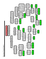
Service Flow Chart
Summary of Contents for 8M51B
Page 2: ...Content 2 11 17 18 19 20 21 28 29 45 46 49 50 57...
Page 3: ...LED 8M51B...
Page 5: ...65 120 140 For 32 LED For 42 LED For 47 LED...
Page 6: ...8 8 6...
Page 7: ...40 40 3 2 1 4 2 50 0 5 80 40 3 12000 26inches is 8 ohm 3 3 3 3 DC Voltage PANEL 12 12...
Page 8: ...40 YES 8 6 46 46 NO NO Standard Spanish Standard 20...
Page 9: ...4 2 4 0 40 70 0 40 70 0 40 40 85 Y0 50 30000...
Page 23: ......
Page 24: ...U16 64M X 16 BIT G DIE DDR3 1333 SDRAM FBGA 96...
Page 25: ...U17 128M X 16 BIT G DIE DDR3 1333 SDRAM FBGA 96...
Page 26: ...U8 16MB SPI FLASH SOP 8 U21 2G BIT CMOS NAND EEPROM TSOPI48...
Page 27: ......
Page 28: ...Main PCB Top Bottom Layer...
Page 29: ...Main PCB Top Bottom Layer...
Page 30: ...8M51B Service Adjustment V0 1...


