


Page 19
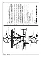
LFS
MOUNTING STRUCTURE GUIDELINE
NO
TES
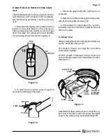
7/8"
suppor
t
rods
located
for
total
suppor
t
of
light,
all
labor
and
mater
ials
for
fa
b
ri
c
a
ti
o
n
s
u
p
p
li
e
d
b
y
G
e
n
e
ra
l
C
o
n
tra
c
to
r.
7
/8
"
nu
ts
a
n
d
w
a
s
h
e
rs
fo
r
suppor
t of SKYTR
ON fixture supplied b
y contr
actor (16 ea.
required).
The
mounting
str
ucture
m
ust
be
attached
to
str
uctur
al
ceiling
and
BRA
CED
T
O
ALLO
W
NO
TWISTING
OR
LA
TERAL
MO
TION
and
shall
be
designed
not
to
pro
vide
a
deg
ree
of
rotation
g
reater
than
tw
o-tenths
of
a
deg
ree
at
the mounting plate or the fixture mounting hub
.
All
4
ar
m
fixture
installations
require
the
mounting
str
ucture
to
be
tested
and comply with SKYTR
ON test jig requirements
.
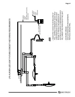
120V
A
C
20A
po
w
er
supply
required
to
junction
bo
x
for
monitor
.
P
o
w
er
cord
with
IEC
female
plug
for
monitor
,
supplied
b
y
SKYTR
ON.
3/4"
conduit
and
minim
um
12A
WG
wire
siz
e
(3
wires
per
lighthead)
required
betw
een
fixture
and
SKYTR
ON
supplied
w
all
control.
All
conduit,
wir
ing,
and
other
electr
ical
mater
ials
as
w
ell
as
installation
labor
for
such
mater
ials
associated
with
the
installation
of
the
SKYTR
ON
surgical
light
to
be
pro
vided
b
y
Electr
ical
Contr
actor
.
All
installations
of
SKYTR
ON
surgical
lights
should
be
under
the
d
ir
e
c
t
s
u
p
e
rv
is
io
n
o
f
a
S
K
Y
T
R
O
N
re
p
re
s
e
n
ta
ti
v
e
.
A
ll
w
ir
in
g
to
b
e
in
a
c
c
o
rd
a
n
c
e
w
it
h
lo
c
a
l
c
o
d
e
s
.
In
s
ta
ll
a
ti
o
n
re
q
u
ir
in
g
p
o
w
e
r
m
o
d
u
le
s
fo
r
flatscreen application require a NEMA 4 enclosure pro
vided b
y others
.
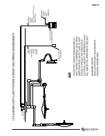
Video
cab
le
for
monitor
routed
through
ar
m
at
installation
to
be
pro
vided
b
y
customer
.
Appro
ximately
15
feet
of
cab
le
is
required
from
mounting
hub
to
monitor
.
TV
light
systems
require
50
feet
RG59U
coaxial
cab
le
from
junction
bo
x
to
camer
a control unit f
aceplate
, supplied b
y SKYTR
ON.
C
O
N
T
R
A
C
T
O
R
H
A
S
F
IN
A
L
R
E
S
P
O
N
S
IB
IL
IT
Y
fo
r
th
e
s
tr
e
n
g
th
a
n
d
stability of the Mounting Str
ucture
.
This is a GENERAL GUIDELINE ONL
Y
.
Consult specific Seismic calculations if applicab
le
.
1.
2.
3.
4.
5.
6.
7.
FINISHED CEILING
CEILING COVER
(SKYTRON SUPPLIED)
3" X 3" ANGLE
SWAY BRACING (4)
7/8" ROD
(4) 1" DIA.
6" PIPE
17" DIA. X 1"
SWAY BRACING
(4) 90° APART
6"
1-1/4"
FLANGE ADAPTOR
(BY OTHERS)
STRUCTURAL ANCHORS
(BY OTHERS)
(6) EQUALLY SPACED HOLES
JUNCTION
BOX
9-1/2"
18" DIA. CEILING COVER
45°- 60°
17" DIA. X 1"
9-1/2"
STRUCTURAL CEILING
BY OTHERS
BY SKYTRON
16.5" DIA. ACCESS HOLE
Summary of Contents for AURORA LED 5 4000K
Page 1: ...REV 9 08 INSTALLATION INSTRUCTIONS LED SERIES SURGICAL LIGHTS...
Page 18: ...Page 16...
Page 20: ...Page 18...
Page 26: ...5085 Corporate Exchange Blvd S E Grand Rapids MI 49512 1 616 656 2900 FAX 1 616 656 2906...
Page 27: ...LED SERIES SURGICAL LIGHTS OPERATORS MANUAL TEC B 0002 REV0 1 09...
Page 47: ...5085 Corporate Exchange Blvd S E Grand Rapids MI 49512 616 656 2900 FAX 616 656 2906...
Page 48: ...PARTS CATALOG LED SERIES SURGICAL LIGHT TEC B 0009 REV3 3 10...
Page 54: ...Page 5 17 Stand Model Support Post Assembly page 40...
Page 65: ...Page 16 6 LED POD ASSEMBLY 57 010307 03mj 3 2 1 4 10 5 6 7 12 13 15 14 15 13 16 8 11 9...
Page 73: ...Page 24 10 LIGHTHEAD ASSEMBLY 1 2 6 7 8 9 11 13 14 12 10 5 3 4 57 031408 06mj...
Page 81: ...Page 32 13 TV LIGHTHEAD ASSEMBLY 1 3 4 5 6 7 8 9 10 11 12 15 17 18 13 16 14 2 5tv 081308 03...
Page 83: ...Page 34 14 WALL CONTROL ASSEMBLY 57 010307 04 1 5 6 9 10 3 2 7 8 4...
Page 85: ...Page 36 15 WALL CONTROL COMPONENTS 57 010307 05 1 2 3 4 5 6 12 13 14 7 8 9 10 11...
Page 91: ...5085 Corporate Exchange Blvd S E Grand Rapids MI 49512 616 656 2900 FAX 616 656 2906...
Page 92: ...MAINTENANCE MANUAL LED SERIES SURGICAL LIGHT 7 07...
Page 93: ......
Page 95: ...Page 2...
Page 110: ...5085 Corporate Exchange Blvd S E Grand Rapids MI 49512 616 656 2900 FAX 616 656 2906...
Page 111: ...REV 8 08 INSTALLATION INSTRUCTIONS LFS SERIES SURGICAL LIGHTS...
Page 133: ...Page 21...
Page 135: ...Page 23...
Page 138: ...5085 Corporate Exchange Blvd S E Grand Rapids MI 49512 1 616 656 2900 FAX 1 616 656 2906...
Page 139: ...LFS SERIES OWNERS MANUAL REV 6 08...
Page 140: ......
Page 142: ...Page 2...
Page 160: ...Page 20...
Page 170: ...5085 Corporate Exchange Blvd S E Grand Rapids MI 49512 1 616 656 2900 FAX 1 616 656 2906...
Page 171: ...INSTALLATION INSTRUCTIONS AUR SERIES SURGICAL LIGHTS TEC B 0006 REV1 8 09...
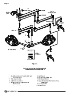
Page 188: ...Page 16 TYPICAL AURORA AUR LIGHT FIXTURE CONDUIT AND WIRING REQUIREMENTS...
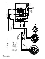
Page 189: ...Page 17 TYPICAL WIRING DIAGRAM...
Page 190: ...Page 18 TYPICAL AURORA AURTV LIGHT FIXTURE CONDUIT AND WIRING REQUIREMENTS...
Page 191: ...Page 19 TYPICAL WIRING DIAGRAM...
Page 196: ...5085 Corporate Exchange Blvd S E Grand Rapids MI 49512 1 616 656 2900 FAX 1 616 656 2906...
Page 197: ...AUR SERIES SURGICAL LIGHTS OPERATORS MANUAL TEC B 0003 REV9 3 10...
Page 198: ......
Page 219: ......
Page 220: ...5085 Corporate Exchange Blvd S E Grand Rapids MI 49512 616 656 2900 FAX 616 656 2906...
Page 221: ...PARTS CATALOG AUR SERIES SURGICAL LIGHT TEC B 0004 REV6 6 10...
Page 222: ......
Page 274: ...5085 Corporate Exchange Blvd S E Grand Rapids MI 49512 616 656 2900 FAX 616 656 2906...
Page 275: ...AUR SERIES SURGICAL LIGHTS MAINTENANCE MANUAL TEC B 0007 REV1 1 10...
Page 276: ......
Page 278: ...Page 2...
Page 292: ...Page 16 TYPICAL WIRING DIAGRAM...
Page 293: ......
Page 294: ...5085 Corporate Exchange Blvd S E Grand Rapids MI 49512 616 656 2900 FAX 616 656 2906...
Page 295: ...TEC B 0008 REV3 3 10 OWNERS MANUAL HANDLE CAMERA SYSTEM...
Page 296: ......
Page 308: ...Page 12 PRECISION HD CAMERA SYSTEM...
Page 310: ...5085 Corporate Exchange Blvd S E Grand Rapids MI 49512 1 616 656 2900 FAX 1 616 656 2906...