


Page 8
UNCRATING PROCEDURE
Open the top of the lighthead box and remove the
packing material, remove the sterilizable positioning
handle and remove lighthead from the crate.
NOTE
Details may vary depending upon model
and support structure fabrication.
ALL fixtures use METRIC fasteners.
INSTALLATION PROCEDURE
Specific seismic information is available for applica-
tions. Refer to seismic drawings.The lighting fixture
should be installed in the following sequence:
1. Mounting Plate
2. Radial Arm Assembly and Ceiling Cover
3. Vertical Support Tubes/ Balance Mechanisms
4. Lightheads
5. Wall Control
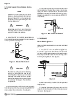
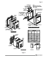
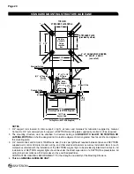
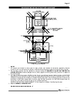
1. Mounting Plate
a. Check the strength and stability of the mount-
ing structure. It should be fabricated of steel and
welded or bolted to the structural ceiling. It should
be braced in a manner that will allow no twisting
or lateral motion. In standard installations a steel
stiffener plate should be used to connect the 3/4"
diameter "all-thread" support rods and to provide
an attachment base for the angle-iron sway bracing.
The 3/4" diameter support rods should be mounted
in a 9-1/2" square pattern and should extend 2-1/4"
below the finished ceiling.
See Mounting Structure
details in the back of this booklet.
b. Install the SKYTRON mounting plate on the
threaded rods between jam nuts. The plate should
normally be located 1-3/8" off the finished ceiling
(measured from the bottom of the plate) and ac-
curately leveled, within 0.1 degree, using a digital
level. Tighten the jam nuts securely. See figure
2.
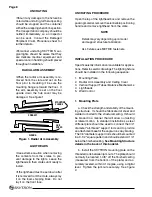
Figure 1. Radial Arm Assembly
LIGhThEADS
•
Use extreme caution when removing
the contents from the crates to pre-
vent damage to the lights. Leave the
lightheads in their crates until ready to
install.
•If the lighthead must be set down after
it is removed from the crate, always lay
it on the foam shipping block. Do not
lay it on the front face.
UNCRATING
•Should any damage to the fixture be
noted while uncrating, further unpacking
should be stopped and the container
with all the wrappings held for inspection.
The transportation company should be
notified immediately so an inspector
can be sent. Consult the Damaged
Shipment Claim Procedure sheet for
further details.
•Personnel uncrating SKYTRON sur
-
gical lights should be aware that they
are delicate medical equipment and
special care in handling should prevail
throughout installation.
RADIAL ARM ASSEMBLy
•When the radial arm assembly is re
-
moved from the crate and set on the
floor prior to mounting it, be sure the
mounting flange is toward the floor. If
the arm assembly is set on the floor
upside down the hub cover may be
damaged. See figure 1.
MOUNTING
FLANGE
CORRECT
WRONG
HUB
COVER
Summary of Contents for AURORA LED 5 4000K
Page 1: ...REV 9 08 INSTALLATION INSTRUCTIONS LED SERIES SURGICAL LIGHTS...
Page 18: ...Page 16...
Page 20: ...Page 18...
Page 26: ...5085 Corporate Exchange Blvd S E Grand Rapids MI 49512 1 616 656 2900 FAX 1 616 656 2906...
Page 27: ...LED SERIES SURGICAL LIGHTS OPERATORS MANUAL TEC B 0002 REV0 1 09...
Page 47: ...5085 Corporate Exchange Blvd S E Grand Rapids MI 49512 616 656 2900 FAX 616 656 2906...
Page 48: ...PARTS CATALOG LED SERIES SURGICAL LIGHT TEC B 0009 REV3 3 10...
Page 54: ...Page 5 17 Stand Model Support Post Assembly page 40...
Page 65: ...Page 16 6 LED POD ASSEMBLY 57 010307 03mj 3 2 1 4 10 5 6 7 12 13 15 14 15 13 16 8 11 9...
Page 73: ...Page 24 10 LIGHTHEAD ASSEMBLY 1 2 6 7 8 9 11 13 14 12 10 5 3 4 57 031408 06mj...
Page 81: ...Page 32 13 TV LIGHTHEAD ASSEMBLY 1 3 4 5 6 7 8 9 10 11 12 15 17 18 13 16 14 2 5tv 081308 03...
Page 83: ...Page 34 14 WALL CONTROL ASSEMBLY 57 010307 04 1 5 6 9 10 3 2 7 8 4...
Page 85: ...Page 36 15 WALL CONTROL COMPONENTS 57 010307 05 1 2 3 4 5 6 12 13 14 7 8 9 10 11...
Page 91: ...5085 Corporate Exchange Blvd S E Grand Rapids MI 49512 616 656 2900 FAX 616 656 2906...
Page 92: ...MAINTENANCE MANUAL LED SERIES SURGICAL LIGHT 7 07...
Page 93: ......
Page 95: ...Page 2...
Page 110: ...5085 Corporate Exchange Blvd S E Grand Rapids MI 49512 616 656 2900 FAX 616 656 2906...
Page 111: ...REV 8 08 INSTALLATION INSTRUCTIONS LFS SERIES SURGICAL LIGHTS...
Page 133: ...Page 21...
Page 135: ...Page 23...
Page 138: ...5085 Corporate Exchange Blvd S E Grand Rapids MI 49512 1 616 656 2900 FAX 1 616 656 2906...
Page 139: ...LFS SERIES OWNERS MANUAL REV 6 08...
Page 140: ......
Page 142: ...Page 2...
Page 160: ...Page 20...
Page 170: ...5085 Corporate Exchange Blvd S E Grand Rapids MI 49512 1 616 656 2900 FAX 1 616 656 2906...
Page 171: ...INSTALLATION INSTRUCTIONS AUR SERIES SURGICAL LIGHTS TEC B 0006 REV1 8 09...
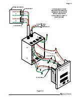
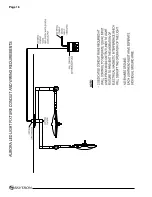
Page 188: ...Page 16 TYPICAL AURORA AUR LIGHT FIXTURE CONDUIT AND WIRING REQUIREMENTS...
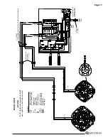
Page 189: ...Page 17 TYPICAL WIRING DIAGRAM...
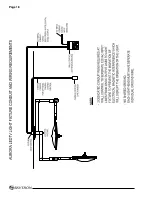
Page 190: ...Page 18 TYPICAL AURORA AURTV LIGHT FIXTURE CONDUIT AND WIRING REQUIREMENTS...
Page 191: ...Page 19 TYPICAL WIRING DIAGRAM...
Page 196: ...5085 Corporate Exchange Blvd S E Grand Rapids MI 49512 1 616 656 2900 FAX 1 616 656 2906...
Page 197: ...AUR SERIES SURGICAL LIGHTS OPERATORS MANUAL TEC B 0003 REV9 3 10...
Page 198: ......
Page 219: ......
Page 220: ...5085 Corporate Exchange Blvd S E Grand Rapids MI 49512 616 656 2900 FAX 616 656 2906...
Page 221: ...PARTS CATALOG AUR SERIES SURGICAL LIGHT TEC B 0004 REV6 6 10...
Page 222: ......
Page 274: ...5085 Corporate Exchange Blvd S E Grand Rapids MI 49512 616 656 2900 FAX 616 656 2906...
Page 275: ...AUR SERIES SURGICAL LIGHTS MAINTENANCE MANUAL TEC B 0007 REV1 1 10...
Page 276: ......
Page 278: ...Page 2...
Page 292: ...Page 16 TYPICAL WIRING DIAGRAM...
Page 293: ......
Page 294: ...5085 Corporate Exchange Blvd S E Grand Rapids MI 49512 616 656 2900 FAX 616 656 2906...
Page 295: ...TEC B 0008 REV3 3 10 OWNERS MANUAL HANDLE CAMERA SYSTEM...
Page 296: ......
Page 308: ...Page 12 PRECISION HD CAMERA SYSTEM...
Page 310: ...5085 Corporate Exchange Blvd S E Grand Rapids MI 49512 1 616 656 2900 FAX 1 616 656 2906...