


Page 18
MOUNTING STRUCTURE GUIDELINE
Foreword
Skytron’s objective is to provide a program and guideline to assist individuals (hospital owners, architects, structural
engineers) responsible for the design of mounting structures.
The mounting structure of a Skytron fixture should always be considered the most important detail of any project prior
to installation. Skytron’s ceiling mounted systems depend upon properly designed and installed mounting structures
to deliver years of dependable, service-free performance.
We realize that individual mounting structures vary in design due to unique structural requirements, physical obstruc-
tions, structural member availability and room layout limitations, to name a few.
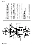
The Mounting Structure Guideline is a successful, proven design. The design consists of a welded, “flanged pipe”
assembly combined with (4) angled sway braces (“kickers”). A structural steel pipe combined with welded steel plates
on each end facilitate its attachment to the structural ceiling and provide an attachment point for the Skytron fixture.
This is a simple effective design that is forgiving to restricting structural conditions that are usually encountered
during fabrication.
This design is also eliminates “guess work” by the steel fabricator when compared to structures that are fabricated
on site with angle iron. In many cases the “flanged pipe” assembly can be pre-fabricated reducing the on-site con-
struction time and eliminating the need to correct structural problems associated with angle iron structures.
The process of building a proper mounting structure can be complemented with Skytron’s continued support on the
project. Once the structures are fabricated, Skytron will perform a visual inspection and on-site consultation followed
by an actual performance test. The performance test of the structure essentially involves hanging a “test jig” from
the structure, and then measuring the amount of rotation that occurs at the mounting plate using an inclinometer
(digital level). The test jig is similar in size, shape, and weight to the Skytron fixtures. In other words, once the test
jig is installed and the proper weights have been added to simulate the product’s moment load, a reading is taken
on the digital level to verify that there is no more that two-tenths of a degree of rotational movement at the mounting
plate.
Rotation of the mounting plate causes the radial arm(s) to become out of level and drift. For a structure to meet
Skytron specifications, we require that the mounting plate does not rotate more that two-tenths of a degree while
loaded with the specified weight and moment.
The testing process should occur in the early stages of construction to provide optimal time if additional reinforcement
is needed on the structure. This should be performed prior to the completion of the finished ceiling.
Skytron’s program is available to help you and provide you with the necessary counseling. However, the final re-
sponsibility to insure that the structure is adequate and meets specification lies with the structural engineer and the
contractor for the project.
Our support services are geared to minimize the effort on all parties involved and to insure a successful product
installation.
We recognize that not all situations will permit the use of this “Pipe Structure”. Please contact SKYTRON with your
special needs so that we may be able to guide you to other alternatives.
Summary of Contents for AURORA LED 5 4000K
Page 1: ...REV 9 08 INSTALLATION INSTRUCTIONS LED SERIES SURGICAL LIGHTS...
Page 18: ...Page 16...
Page 20: ...Page 18...
Page 26: ...5085 Corporate Exchange Blvd S E Grand Rapids MI 49512 1 616 656 2900 FAX 1 616 656 2906...
Page 27: ...LED SERIES SURGICAL LIGHTS OPERATORS MANUAL TEC B 0002 REV0 1 09...
Page 47: ...5085 Corporate Exchange Blvd S E Grand Rapids MI 49512 616 656 2900 FAX 616 656 2906...
Page 48: ...PARTS CATALOG LED SERIES SURGICAL LIGHT TEC B 0009 REV3 3 10...
Page 54: ...Page 5 17 Stand Model Support Post Assembly page 40...
Page 65: ...Page 16 6 LED POD ASSEMBLY 57 010307 03mj 3 2 1 4 10 5 6 7 12 13 15 14 15 13 16 8 11 9...
Page 73: ...Page 24 10 LIGHTHEAD ASSEMBLY 1 2 6 7 8 9 11 13 14 12 10 5 3 4 57 031408 06mj...
Page 81: ...Page 32 13 TV LIGHTHEAD ASSEMBLY 1 3 4 5 6 7 8 9 10 11 12 15 17 18 13 16 14 2 5tv 081308 03...
Page 83: ...Page 34 14 WALL CONTROL ASSEMBLY 57 010307 04 1 5 6 9 10 3 2 7 8 4...
Page 85: ...Page 36 15 WALL CONTROL COMPONENTS 57 010307 05 1 2 3 4 5 6 12 13 14 7 8 9 10 11...
Page 91: ...5085 Corporate Exchange Blvd S E Grand Rapids MI 49512 616 656 2900 FAX 616 656 2906...
Page 92: ...MAINTENANCE MANUAL LED SERIES SURGICAL LIGHT 7 07...
Page 93: ......
Page 95: ...Page 2...
Page 110: ...5085 Corporate Exchange Blvd S E Grand Rapids MI 49512 616 656 2900 FAX 616 656 2906...
Page 111: ...REV 8 08 INSTALLATION INSTRUCTIONS LFS SERIES SURGICAL LIGHTS...
Page 133: ...Page 21...
Page 135: ...Page 23...
Page 138: ...5085 Corporate Exchange Blvd S E Grand Rapids MI 49512 1 616 656 2900 FAX 1 616 656 2906...
Page 139: ...LFS SERIES OWNERS MANUAL REV 6 08...
Page 140: ......
Page 142: ...Page 2...
Page 160: ...Page 20...
Page 170: ...5085 Corporate Exchange Blvd S E Grand Rapids MI 49512 1 616 656 2900 FAX 1 616 656 2906...
Page 171: ...INSTALLATION INSTRUCTIONS AUR SERIES SURGICAL LIGHTS TEC B 0006 REV1 8 09...
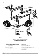
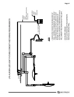
Page 188: ...Page 16 TYPICAL AURORA AUR LIGHT FIXTURE CONDUIT AND WIRING REQUIREMENTS...
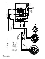
Page 189: ...Page 17 TYPICAL WIRING DIAGRAM...
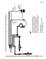
Page 190: ...Page 18 TYPICAL AURORA AURTV LIGHT FIXTURE CONDUIT AND WIRING REQUIREMENTS...
Page 191: ...Page 19 TYPICAL WIRING DIAGRAM...
Page 196: ...5085 Corporate Exchange Blvd S E Grand Rapids MI 49512 1 616 656 2900 FAX 1 616 656 2906...
Page 197: ...AUR SERIES SURGICAL LIGHTS OPERATORS MANUAL TEC B 0003 REV9 3 10...
Page 198: ......
Page 219: ......
Page 220: ...5085 Corporate Exchange Blvd S E Grand Rapids MI 49512 616 656 2900 FAX 616 656 2906...
Page 221: ...PARTS CATALOG AUR SERIES SURGICAL LIGHT TEC B 0004 REV6 6 10...
Page 222: ......
Page 274: ...5085 Corporate Exchange Blvd S E Grand Rapids MI 49512 616 656 2900 FAX 616 656 2906...
Page 275: ...AUR SERIES SURGICAL LIGHTS MAINTENANCE MANUAL TEC B 0007 REV1 1 10...
Page 276: ......
Page 278: ...Page 2...
Page 292: ...Page 16 TYPICAL WIRING DIAGRAM...
Page 293: ......
Page 294: ...5085 Corporate Exchange Blvd S E Grand Rapids MI 49512 616 656 2900 FAX 616 656 2906...
Page 295: ...TEC B 0008 REV3 3 10 OWNERS MANUAL HANDLE CAMERA SYSTEM...
Page 296: ......
Page 308: ...Page 12 PRECISION HD CAMERA SYSTEM...
Page 310: ...5085 Corporate Exchange Blvd S E Grand Rapids MI 49512 1 616 656 2900 FAX 1 616 656 2906...