background image

10

SK650-2

SKOPE Gen2: Single Door Chiller

2.3 Loading

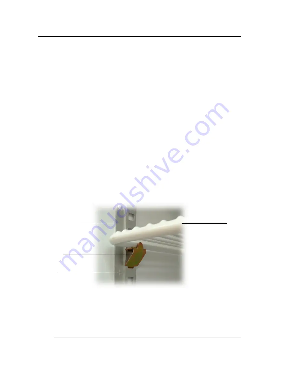
The shelves may be positioned at different heights to suit various 
products. Each shelf is held in place with four shelf clips. Always 
ensure that the shelf clips are securely engaged in each of the four 
shelf support strips. The support strips are marked with a ‘+’ for easy 
location of the shelf clips (see Figure 1 below).
When loading the shelves with product:
• ensure to allow air space around all packages etc, for even 

cooling and efficient operation.

• leave an airspace of at least 75mm (3") above packages etc. on 

the top shelf.

• do not allow products to overhang the front of the shelf as this 

could prevent the door from shutting or cause glass breakage.

OPERATION

2

Figure 1: Shelf Clip

Shelf Support Strip

Shelf Clip

‘+’ Mark

Shelf 

Summary of Contents for SK650-2

Page 1: ...SK650 2 SKOPE Gen2 Single Door Chiller Vertical Display and Storage Operating and Service Manual MAN0516 Rev 3 0 August 2005 edition ...

Page 2: ......

Page 3: ...church New Zealand Freephone 0800 947 5673 Fax 03 983 3896 E mail enquiry skope co nz Website www skope co nz Australia SKOPE AUSTRALIA PTY LTD A C N 000 384 270 PO Box 7543 Baulkham Hills B C NSW 2153 Australia Freephone 1800 121 535 Fax 1800 121 533 E mail enquiry skope com au Website www skope com au CONTACT ADDRESSES i ...

Page 4: ...perating and Service Manual MAN0516 Rev 3 0 August 2005 edition Copyright 2003 SKOPE Industries Limited All rights reserved SKOPE and CYCLONE are registered trademarks of SKOPE Industries Limited SKOPE Industries Limited reserve the right to alter specifications without notice ii ...

Page 5: ... 2 4 Cleaning 11 3 ELECTRONIC CONTROLLER 3 1 Controller Display 12 3 2 Controller Operation 13 3 3 Programming Controller 14 3 4 Parameters 17 3 5 Alarm Displays 18 3 6 Replacement 19 4 SERVICE INSTRUCTIONS 4 1 Interior Side Light 23 4 2 Door 24 4 3 Sign Unit 28 4 4 Refrigeration Unit 33 4 5 Pressure Temperature Chart 42 4 6 Troubleshooting Chart 44 TABLE OF CONTENTS iii ...

Page 6: ...ING DIAGRAMS 5 1 Model SK650 2 Type V60BA 48 5 2 Model SK650 2 Type V60BB 50 6 SPARES 6 1 Cabinet Assembly 52 6 2 Interior Side Light 53 6 3 Door 54 6 4 Sign Unit 55 6 5 Refrigeration Unit 56 6 6 Refrigeration Unit Junction Box 57 TABLE OF CONTENTS ...

Page 7: ...egral Cyclone refrigeration unit Nominal capacity 581 Watts Compressor Electrolux GLY90RA Refrigerant R134a 450 grams Electrical 230 240 Volts a c 50 Hz single phase power supply Run Amps 2 77 Amps Lighting Single or twin sidelights 35 Watt T5 fluorescent tube OSRAM FH 35W 860 Daylight Ø16mm x 1450mm Illuminated Sign 1 x 14 Watt T5 fluorescent tube OSRAM FH 14W 860 Daylight Ø16mm x 550mm Door Self...

Page 8: ... any opening Only use this appliance with voltage specified on the rating label Ensure adequate ventilation of the SKOPE refrigeration unit Be careful not to touch moving parts and hot surfaces Regulations require that all electrical work be carried out by authorised persons For your own safety and that of others ensure this is done If the supply cord becomes damaged it must be replaced by a SKOPE...

Page 9: ...uld switch off when the cabinet internal temperature reaches approximately 2 C and on again at approximately 4 C The internal cabinet air will continue to circulate at all times Electronic controller The electronic controller will either display the internal cabinet tem perature or the controller set point The compressor on LED will indicate that the compressor is operating see Figure 2 on page 12...

Page 10: ...ort strips are marked with a for easy location of the shelf clips see Figure 1 below When loading the shelves with product ensure to allow air space around all packages etc for even cooling and efficient operation leave an airspace of at least 75mm 3 above packages etc on the top shelf do not allow products to overhang the front of the shelf as this could prevent the door from shutting or cause gl...

Page 11: ...mmended that on a regular basis the cabinet be isolated from mains power supply and a vacuum cleaner used to remove dust and fluff from the condenser coil The condenser coil should be brushed clean once a month and blown clean by qualified service personnel every six months The condenser coil is situated behind the sign unit To access the condenser coil 1 Disconnect the cabinet from the mains powe...

Page 12: ...alue 4 DOWN Press to see the minimum stored temp In programming mode it browses the parameter codes or decreases displayed value 5 Compressor on LED indicator 6 Defrost cycle on LED indicator 7 Set Point displayed LED indicator 8 Decimal point LED indicator Key Combinations Press both keys simultaneously to lock and unlock the keypad Press both keys simultaneously to enter the programming mode Pre...

Page 13: ...KOPE electronic controller controls and displays the cabinet temperature The preset temperature setting controls internal air temperature between 2 C and 4 C The electronic controller also signals and records temperature alarms together with their duration and maximum value reached see Table 5 on page 18 To ensure efficient operation the electronic controller has a built in minimum off cycle time ...

Page 14: ...ill be possible only to see the Set Point or maximum or minimum temperature stored 3 If a key is pressed for more than 3 seconds the PoF message will be displayed To display the Set Point Press and immediately release the SET key The display will show the Set Point value and the Set Point LED will be highlighted To change the Set Point 1 Push and hold the SET key for more than 2 seconds 2 The valu...

Page 15: ...g parameter 6 To exit Press both the SET and UP keys or wait 15 seconds without pressing any keys 7 To lock in new parameter value after one minute operation disconnect and reconnect cabinet into the mains power supply NOTES 1 The Set value is stored even when the procedure is exited by waiting for the time out to expire 2 Dependent on customer requirements the SKOPE electronic controller has diff...

Page 16: ...s and release the UP key 2 The Ht message will be displayed followed by the maximum temperature recorded 3 Press the UP key again or wait 5 seconds to restore the normal display To reset the maximum and minimum temperature 1 Press and hold the SET key for more than 3 seconds while the maximum or minimum temperature is displayed The rSt message will be displayed 2 To confirm the operation the rSt m...

Page 17: ...t DEF Displaying during defrost dAd 20 Minutes 0 255 Maximum display delay after defrost ALARM PARAMETERS ALc Ab rE Ab Temperature alarms configuration ALU 12 C 150 C Maximum temperature alarm ALL 2 C 50 C ALU Minimum temperature alarm AtH 1 C 0 1 C 25 5 C Differential for temperature alarm in cabinet ALd 240 Minutes 0 255 Temperature alarm delay dAO 24 0 Mins 23 5 Hours Delay of temperature alarm...

Page 18: ... agent Faulty Ambient probe internal cabinet return air Faulty High Temperature probe condenser Internal cabinet LOW temperature alarm Internal cabinet HIGH temperature alarm Table 5 Controller Display Alarms Note The refrigeration system and cabinet lighting shut down with P1 P2 and CSd alarms Alarm Recovery Condenser over temperature alarm COH recovers when the condenser is either cleaned or coo...

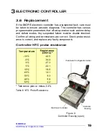
Page 19: ...ected failure must be double checked Confirm all wiring and terminations are correct Check probe resist ance is correct and replace any faulty components Controller NTC probe resistance Temperature Resistance Ohms 10 C 42 5 5 C 34 0 0 C 27 3 5 C 22 1 10 C 18 0 20 C 12 1 30 C 8 3 40 C 5 8 50 C 4 2 Tolerance plus or minus 2 4 Table 6 NTC Probe Resistance ELECTRONIC CONTROLLER 3 Figure 3 Controller H...

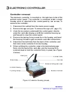
Page 20: ...t the controller housing up and forward to clear the control panel 4 Remove the two top fixing screws from the housing and bend the housing lid back to gain access to controller connections 5 Disconnect the terminals from the back of the controller and then remove the controller from the housing 6 When re fitting the controller ensure the terminals engage firmly into the back of the controller and...

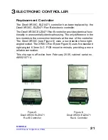
Page 21: ...he only difference in the two models is the connection terminals at the rear of the controller The Dixell XR30C see Figure 6 uses a low insertion force right angled socket The XR30C Rev B see Figure 5 uses five standard right angled 6 3mm Q C PCB mount terminals providing a more reliable connection This change is effective from February 2005 cabinet serial no A050212714 ELECTRONIC CONTROLLER 3 Fig...

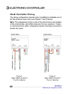
Page 22: ...s see Figures 7 and 8 below Note The arrangement of the order of the connections and position of the external loop wire differs between the two variations Howev er the connections at the refrigeration system electrical junction box remain the same Figure 8 Dixell XR30C ELZ0471 Rev A Controller Figure 7 Dixell XR30C ELZ0471 Rev B Controller ELECTRONIC CONTROLLER 3 ...

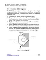
Page 23: ...uminium housing and push the diffuser back to gain access to the light see Figure 9 below 3 The fluorescent tube can now be removed Revolve the tube until the pin position allows withdrawal 4 When refitting the new fluorescent tube ensure the printing on the tube is at the top as the orientation of the tube is important 5 When refitting the diffuser engage back section into side light housing and ...

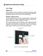
Page 24: ...oor gasket retainer extrusion and may be removed for repair or replacement simply by peeling from frame starting at a corner see Figure 10 below The new door gasket when being fitted may be lightly lubricated with a clear silicone grease or similar compound This will lessen the possibility of the gasket rolling Should the gasket be out of shape when in place use hot air i e from hair drier to real...

Page 25: ... 5mm steel rod increase the tension by turning the capstan in the direction the door closes 3 Once adequate tension has been achieved re insert the split pin through the hole in the hinge bracket to lock in position 4 To check door tension hold the door open approximately 100mm and let go of the door The door should gently close with the door gasket forming an air tight seal with the cabinet In th...

Page 26: ...lear the hinge hole 3 Remove existing capstan and bush from old torsion bar 4 Thread the capstan complete with the bush over the round hook end of the new torsion bar see figure 12 Ensure the aluminium tube moves freely up and down the torsion bar 5 Fit the new torsion bar assembly into the door frame When the torsion bar is correctly installed the capstan should not turn 6 Lightly tap bottom of c...

Page 27: ... the door will need supported until the bottom hinge is fitted 2 Locate bottom hinge onto door capstan and attach to cabinet 3 Check alignment with other doors and adjust as necessary 4 Re tension the door see Door tension on page 25 Hinge reversal The glass door can be hinged on either the left or right hand side To reverse the door hinging opposite hand top and bottom hinges are required 1 Remov...

Page 28: ... for this procedure To remove the sign panel 1 Disconnect cabinet from the power supply 2 Start at one of the top corners of the sign unit and pull the sign panel out from under the sign top cover see Figure 13 below 3 Work along the length of the sign unit pulling the sign panel out as you go 4 Carefully remove the sign panel away from the sign unit 5 The fluorescent tube can now be accessed for ...

Page 29: ...ts neatly into the corner notch see Figure 14 on page 28 4 Use your thumbs to push the sign panel under the top cover working progressively along the full length of the panel Ensure the sign panel engages into the sign top along the full length of the sign unit 5 Ensure both the sign end strips fit neatly into the top and bottom corner notches see Figure 14 on page 28 SERVICE INSTRUCTIONS 4 Figure...

Page 30: ...Sign Unit on page 31 3 Remove the curved sign panel see To replace the fluorescent tube on page 28 4 Remove the centre tie wire see figure 15 on page 29 5 Remove the fluorescent tube to avoid it being damaged 6 Remove the sign wiring cover by undoing the four screws from the rear of the sign unit 7 The electronic ballast mounted on the back of the sign wiring cover can now be accessed for replacem...

Page 31: ... box see Figure 17 below 3 Loosen and turn the sign retaining clip on the top of each of the sign side panels see Figure 18 below 4 Lift the sign unit up to separate the sign from the sign sides 5 The sign unit can now be removed from the cabinet 6 When refitting the sign unit it s easier to plug the sign ENSTO plug into the unit junction box before attaching the sign to the side panels SERVICE IN...

Page 32: ...ifting up to disengage from the side panels see Figure 19 below 4 Loosen the two keyhole screws holding each side panel to the cabinet top see Figure 20 below 5 From the front of the cabinet push the side panels back to disengage the keyholes 6 The sign side panels can now be lifted off the cabinet 7 When refitting the side panels ensure to refit the sign back panel and to tighten the keyhole scre...

Page 33: ...de of evaporator box 6 By using the diagonal white handles on either side of unit lift the unit up and off the cabinet Avoid damage to the underside sealing strip by not dragging the refrigeration unit If damage to the seal occurs it must be repaired prior to re installation To re install the refrigeration unit 1 Ensure all cables capillaries etc are secured away from moving or hot parts before re...

Page 34: ...or platform about 1 metre high are suggested to allow the unit to be safely lifted carried and put down at waist height SERVICE INSTRUCTIONS 4 Figure 21 Refrigeration Unit Unit Junction Box Unit Handle Condenser Fan Motor Compressor Mains Supply Flex Evaporator Box Unit Retaining Bracket Cabinet and Sign Supply Sockets Condenser Coil Unit Base Electronic Controller ...

Page 35: ...it junction box 1 Disconnect the cabinet from the mains power supply 2 Undo the top and bottom screws from the unit junction box and remove the cover leaving the cover Earth wire still attached 3 All electrical connections can now be accessed 4 Ensure the unit junction box cover is replaced after servicing SERVICE INSTRUCTIONS 4 Figure 22 Unit Junction Box with cover removed Fan Motor Flexes Mains...

Page 36: ...t the terminals 4 Withdraw condenser fan motor flex out of the unit junction box 5 Undo the two top fixing screws from the mounting bracket 6 Remove the clamp holding the liquid drier line to top of the fan shroud and carefully pull the line forward enough to allow the removal of the condenser fan motor assembly 7 Remove complete condenser fan motor assembly 8 Remove fan blade and undo four screws...

Page 37: ...top screws from the mounting bracket and remove complete evaporator fan motor assembly see Figure 24 6 Undo two screws from motor junction box and disconnect flex 7 Remove the fan blade and undo four screws holding fan motor 8 Replace the fan motor capacitor inside the unit junction box 9 When refitting the evaporator fan motor assembly reseal the flex hole in evaporator box before refitting the e...

Page 38: ...uld be brushed clean once a month and blown clean by qualified service personnel every six months The condenser coil is situated behind the sign unit To access the condenser coil 1 Disconnect the cabinet from the mains power supply 2 Loosen the sign retaining clip on the top of each side panel 3 Lift the sign unit up to disengage from the sign sides 4 Disconnect the sign ENSTO plug from the unit j...

Page 39: ...and accumulator must be frosting Compressor at suction inlet will be cold and sweating If these conditions are not met the system is faulty either short of refrigerant compressor not pumping efficiently or capillary restric tion The system must then be opened see Refrigerant R134a Handling Precautions section and gauges temporarily fitted i e either temporarily fit line piercing valves or braze in...

Page 40: ...ere are different methods to proving pumping efficiency If the test is performed with a system charged with refrigerant a deep vacuum will not be achieved Capillary restriction With a totally blocked capillary there will be no refrigeration effect A partially blocked capillary may have similar symptoms to a system being short of refrigerant Flush a restricted capillary with dry nitro gen If the ca...

Page 41: ...pecially compressor must only be open for the very minimum time to prevent moisture ingression All parts required for servicing must be at hand before the system is opened and there should be no interruption until the system is on the vacuum pump or hermetically sealed The system must not be open for longer than 20 minutes max The drier must be replaced every time the system is opened Clean work p...

Page 42: ...9 7 2 236 34 3 2 16 56 8 1 248 36 5 0 15 63 9 1 261 38 6 8 14 69 10 0 274 40 8 6 13 77 11 0 288 42 10 4 12 84 12 0 302 44 12 2 11 91 13 0 316 46 14 0 10 99 14 0 331 48 15 8 9 107 16 0 346 50 17 6 8 116 17 0 361 52 19 4 7 124 18 0 377 55 21 2 6 133 19 0 393 57 23 0 5 142 21 0 410 59 24 8 4 151 22 0 427 62 26 6 3 161 23 0 445 65 28 4 2 171 25 0 463 67 30 2 1 181 26 0 481 70 32 0 0 192 28 0 500 73 33...

Page 43: ... or replace control Thermostat off due to cold location Relocate control Wiring improper or loose Check wiring against diagram 3 Compressor will not start hums but trips on overload protector Improperly wired Check wiring against diagram Low voltage to unit Determine reason and correct Start capacitor defective on CSIR or CSR motor Determine reason and replace Run capacitor defective on PSC motor ...

Page 44: ... tight May be lubrication Replace compressor 5 Compressor starts and runs but short cycles on overload protector relay may chatter on RSIR CSIR and CSR motors Additional current passing through overload protector Check wiring diagram Check for added fan motors etc connected to wrong side of protector Low voltage to unit Determine reason and correct Overload protector defective Check current replac...

Page 45: ...Evaporator has excessive load Establish load within limits Evaporator coil iced Defrost evaporator check refrigeration Check thermostat Check door closing seals etc Check defrost Restriction in refrigeration system Determine location and clear restriction Flush with dry nitrogen Replace component if blockage will not clear Dirty condenser Clean condenser Advise client how to regularly clean conden...

Page 46: ...ne correct size and replace 9 Relay defective or burned out Incorrect relay Check and replace Line voltage too high or too low Determine reason and correct Excessive short cycling Determine reason and correct Relay being influenced by loose vibrating mount Remount rigidly 10 Suction line frosted Evaporator fan not running Determine reason and correct Overcharge of refrigerant capillary systems Cor...

Page 47: ...47 SK650 2 SKOPE Gen2 Single Door Chiller Notes SERVICE INSTRUCTIONS 4 ...

Page 48: ...48 SK650 2 SKOPE Gen2 Single Door Chiller 5 1 Model SK650 2 Type V60BA WIRING DIAGRAMS 5 ...

Page 49: ... Unit Junction Box 8 Capacitor 24 Cabinet Step Wiring 9 Evaporator Fan Motor anti clockwise LE 25 3 Way Connector 2 10 Evaporator Fan Motor clockwise LE 26 Electronic Controller 11 Condenser Fan Motor clockwise LE 27 Cabinet Temp Probe 12 3 Way ENSTO Socket 2 28 Condenser Temp Probe 13 3 Amp Fuse 29 Glass Door Assembly 14 Mains Terminal Block 30 Door Frame Heater Wire 15 RFI Capacitor optional 31 ...

Page 50: ...50 SK650 2 SKOPE Gen2 Single Door Chiller 5 2 Model SK650 2 Type V60BB WIRING DIAGRAM 5 ...

Page 51: ...s y 24 Cabinet Step Wiring 8 Capacitor 25 3 Way Connector 4 9 Evaporator Fan Motor anti clockwise LE 26 Electronic Controller 10 Evaporator Fan Motor clockwise LE 27 Cabinet Temp Probe 11 Condenser Fan Motor clockwise LE 28 Condenser Temp Probe 12 3 Way ENSTO Socket 2 29 Glass Door Assembly 13 3 Amp Fuse 30 Door Frame Heater Wire 14 Mains Terminal Block 31 Side Light Assembly 15 RFI Capacitor opti...

Page 52: ...ion Box Single Side Light Twin Side Light V60BA G29 V60BB G29 Single Electronic Ballast ELZ0605 Double Electronic Ballast ELZ0606 Junction Box Base V60BA G30 GT Junction Box Cover V60BA G31 GT Cabinet Supply Flex V60BA X03 ENSTO 3 Pole Plug ELZ0500 3 Ballast Cover V60BA E06 Shelf WRKV6000 J70 Shelf Bracket V0973 99 Shelf Support Strip ALXV5000 150 Swivel Castor SXX4339 SPARES 6 ...

Page 53: ...r 6 2 Interior Side Light Part Description SKOPE P No Customer P No T5 Side Light Assembly L H V50BA L85 32 T5 Side Light Assembly R H V50BA R85 32 35 Watt T5 Fluorescent Tube ELL0604 T5 Lampholder ELZ0600 Side Light Cover V50BA E71 SPARES 6 ...

Page 54: ... Door Gasket GKT0432N Door Heater Element ELE9932 Torsion Bar Assembly REF5014 Bush PLM5075 Capstan TUR5100 Split Pin FAS5076 Gasket Retainer Vertical V50BA 765 Gasket Retainer Horizontal V6000 766 Top Hinge Blank L H V80BA 390B Top Hinge Assembly R H V50BA 388 Top Hinge Assembly L H V50BA 389 Bottom Hinge R H V50BA 393 Bottom Hinge L H V50BA 394 SPARES 6 ...

Page 55: ... H V50BA S24 Sign Reflector V60BA C23 Curved Sign Panel PVC V6000 S27V Wiring Cover V60BA C26 32 Sign Side R H V50BA 182R Sign Side L H V50BA 182L Sign Top Bottom Panel V60BA S26 Sign Back Panel V60BA C53 Sign Panel Edge Strip RUE3704CL ME 14 Watt T5 Fluorescent Tube ELL0601 T5 Lamp Holder ELZ0600 Single Electronic Ballast ELZ0605 ENSTO 3 Pole Plug ELZ0500 3 SPARES 6 ...

Page 56: ...7 32 Evaporator Assembly UT40AA R39 Evaporator Coil CLS0752 Evaporator Motor ELM9917 Motor Capacitor ELC9142NC R H Fan Blade CW FAN4100 L H Fan Blade ACW FAN4101 Suction Line UT40AA 379A Compressor Electrolux CPR0464P Electrolux Relay ELR9943NC Run Capacitor ELC9941NC Start Capacitor ELC9942NC Overload Protector PLM9944NC Drier DRY8783 DIXELL Electronic Controller ELZ0471SP DIXELL NTC Probe ELZ047...

Page 57: ... Junction Box Assembly UT40AA R86 Junction Box Base UT40AA R87 GT Junction Box Cover UT40AA R88 GT Motor Capacitor ELC9142NC 3 Amp Ceramic Fuse ELZ9654 Fused Terminal Block ELZ9655 ENSTO Socket ELZ0499 3 ENSTO Panel Adaptor PLM0497 3 Controller Flex Assembly UT40AA K19 Mains Flex UE40AA E53 Junction Box SPARES 6 ...

Reviews: