13
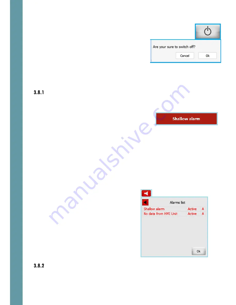
Standby: turns the system in Standby mode. An
“Are You Sure” screen appears when this button is
touched. Touch “OK” to turn the system in Standby
mode.
3.8
Alerts
Alerts basics
If a value goes over a minimum or maximum limit, or functional failure occurs, an
alert will be triggered. This causes the following things to happen:
•
A flashing text indicator is shown in a
prominent position on the screen
•
The alert state is logged to an alert list, with the time stamp of the alert status
change
•
The potential free relays in the Interface Unit can be activated (depending
on the settings of each relay function, ref section 6.6.4). These can be used
to trigger audible alerts or set alerts in other systems.
To acknowledge an alert, causing the on-screen warning to disappear, touch the
flashing warning box. More than one alert condition could be in place at the same
time, so it may be necessary to repeat this procedure to acknowledge the other
alerts.
The alert parameters are adjusted, controlled and monitored using the Alert
screens, ref sections 4.4 and 5.4
The “loudspeaker” button is on provided in the
second line of each screen. The color of the
button depends on the existing alarm
conditions. If any alarm condition exists – the
button is red, otherwise – grey.
Touch the “loudspeaker” button and the active
alarms list will appear.
Alarm status can be “Active” or “Inactive”
Acknowledge status can be “A”
(Acknowledged) or “N” (Not acknowledged)
This way it is always possible to check the alarms
status after they has been acknowledged.
Generic alert conditions
There are several alert types, which are common for both echosounder and speed
log systems.
Summary of Contents for EMES60
Page 8: ...7 2 3 System Structure ...


