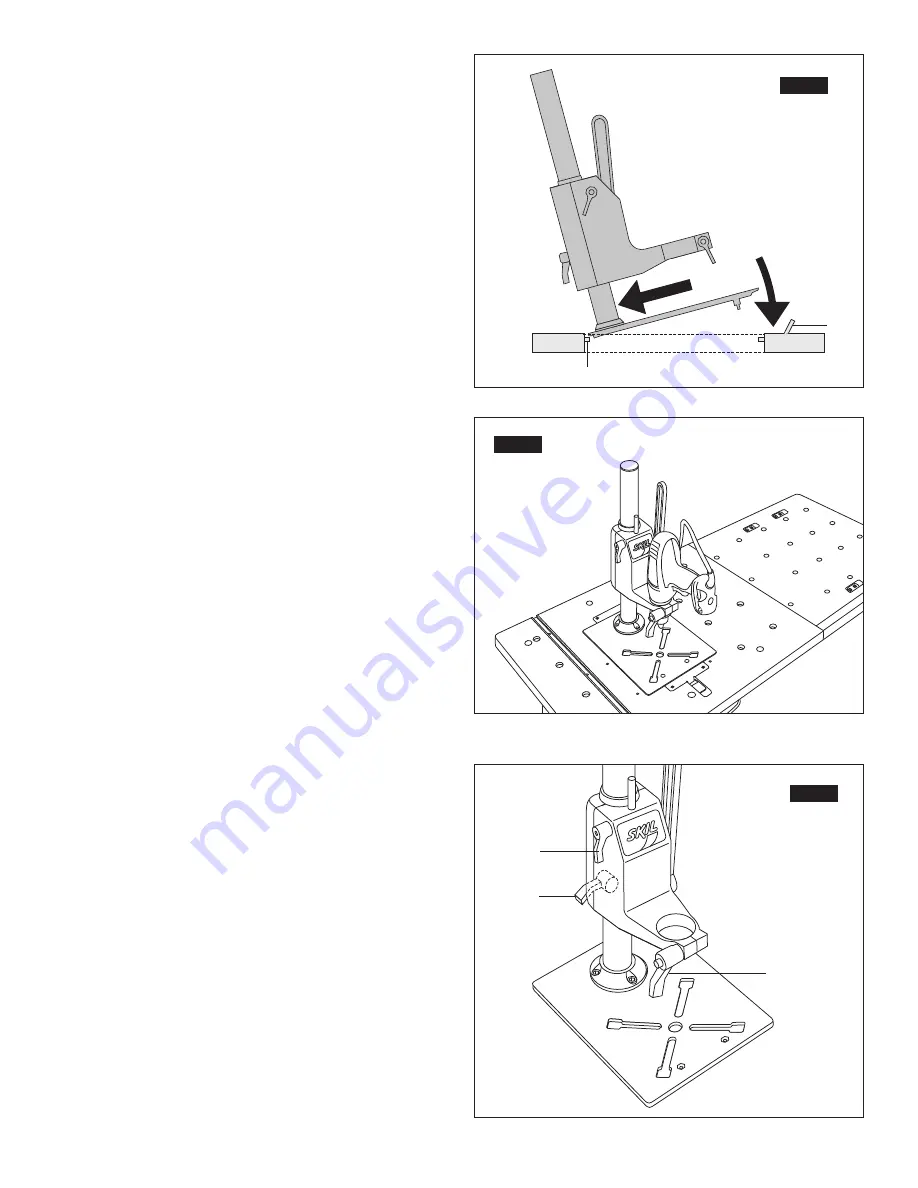
2. Slip tabs on the back edge of the base plate into rear of the table
opening (Fig. 3).
3. Lower front edge of the base plate into opening and lower the
red latch lever
Y
. (Fig. 4)
Adjusting the Height:
1. Loosen the column clamping lever (3) and slide the tool mount
to the desired height. Swinging to the side is possible (Fig. 5).
2. Retighten the column clamping lever (3).
Adjusting the Depth Stop:
1. Once the column height has been set - loosen the depth
clamping lever (2) and drill a test hole (Fig. 5).
2. When the desired depth is located, retighten the depth clamping
lever (2).
Note –
The drilling lever can be adjusted to the desired working
position. For this purpose, remove the plastic bolt cover (DP3) and
loosen the lever attachment bolt (DP2). Once the desired position
is established, retighten the lever attachment bolt and replace the
plastic bolt cover (DP3) (Fig. 1).
Cable Storage:
On the back side of the drill press tool mount, power cord storage
is provided to keep excess cord away from the work area.
18.
1
2
FIG. 3
Y
X
FIG. 4
FIG. 5
2
3
1
(Tool Not Included)/ (Outil non joint)
(Herramienta no incluida)


