


2
F
ig. 14
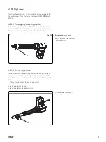
4.8.3 Electrical pinch protection
MAX3 and MAX6
2
1
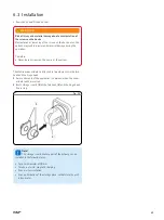
Fig. 15
The electrical pinch protection consists of a hinge head with an elon-
gated hole (
1
), an integrated control pin (
2
) and a micro switch,
which turns off the device when it moves against the effective direc-
tion. In the event of a jam, the pin is lifted from the fastening bold
and triggers the activation of the turn-off function.
!
Note!
It is recommended that this option is not used in
connection with an impulse transmitter. Additional information
in conjunction with the quick adjustment feature (
†
Chapter
“Operation”
).
Electrical pinch protection
Quick adjustment via Bowden cable (2)
32
Summary of Contents for Matrix MAX1
Page 4: ...4 ...
Page 87: ...Notes 87 ...


