


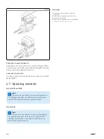


4.2 Brief description
1
2
3
4
5
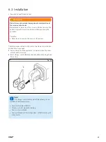
Fig. 7
The actuator is implemented in an application and is exclusively
forthe dynamic centric compression- or tensile-loaded lift.
The linear actuator consists of a motor part (
1
) and a linear
unit(
5
), connected with each other by a bayonet joint.
The actuator consists of a direct current motor with worm gear
which sets in motion a trapezoidal sliding spindle system with shaft
joint (type B and C) or ball bearing spindle system (type A). Via the
ball screw mount the trapezoidal sliding spindle or ball bearing spin-
dle system transforms the rotation of the gear into a linear motion
of the actuator (
3
).
The hinge head (
2
) and the fork head (
4
) transmit the actuator
power to both sides of the application.
26
Summary of Contents for Matrix MAX1
Page 4: ...4 ...
Page 87: ...Notes 87 ...


