


The third party control must enable the drive to draw currents up to
25 A for 200 ms after switching on (start-up current). The access
power shut-off feature can also be temporarily de-activated for this
purpose.
The operating voltage of the MAX1 and MAX3 actuators is
24–30 V DC. The no-load voltage of 36 V DC must not be exceeded.
After the system has been installed , ensure electro-magnetic
compatibility. The operating time and duty cycle of the MAX
actuators may not be exceeded.
Push-to-run operation (recommended): The actuator operates as
long as the switch is pressed. If the device does not have signals to
indicate operation, and depending on the application, it is recom-
mended to ha an operational signal installed in the third party con-
trol unit.
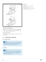
4.6 Connections
!
Note!
The current cut-off has to be set differently if the main
load direction is in pull mode. Consult the technical data or
datasheet in this manual, for maximum power consumption
values for each type
!
Note!
The third party power supply must have an isolation
between the primary and secondary circuits according to
2 MOPP, and provide a non-grounded secondary circuit
1
2
3
4
5
6
7
8
9
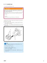
Fig. 10
Matrix MAX1 and MAX3
1
Connection to an external control
(jack or DIN-8 plug)
A low voltage plug (
1
) connects the device to
the power supply via an external SKF control.
29
Summary of Contents for Matrix MAX1
Page 4: ...4 ...
Page 87: ...Notes 87 ...


