5
ENGLISH
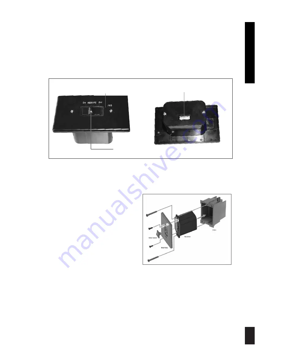
The Proflame Receiver (Fig. 3) connects directly to the gas valve with the wiring harness provided.
The Receiver is powered by 4 AA type batteries. The Receiver accepts commands via radio
frequency from the Transmitter to operate the appliance in accordance with the particular
Proflame system configuration. The Receiver’s three position slider switch can be set to one of
three positions: ON (manual override), Remote (Remote control) or OFF.
Fig. 3:
Proflame Receiver body.
12 PIN terminal
RECEIVER
INSTALLATION
The Receiver can be placed inside a standard
junction type wall box or a low temperature
area of the appliance.
Wall Mounting
1. Connect the wiring harness to the back of
the Receiver.
2. Install the Receiver in the Junction box
using the existing J box screws. (Fig. 4)
3. Insert the 4 AA type batteries in the battery
compartment with the correct polarity.
4. Place the slider into the cover plate.
5. Put the Receiver switch in the “OFF”
position.
6. Make sure the Receiver and cover plate
words “ON” and “UP” are on the same side.
7. Align the slider with the switch on the Receiver and couple the switch into the slider.
8. Align the screw holes.
9. Using the two (2) screws provided secure the cover plate to the Receiver.
Hearth Mounting
1. Connect the wiring harness to the back of the Receiver.
2. Install the 4 AA type batteries in the battery compartment with the correct polarity.
3.Make sure the Receiver and cover plate words “ON” and “UP” are on the same side.
4. Place the slider into the cover plate.
5. Align the slider with the switch on the Receiver and couple the switch into the slider.
6. Using the two (2) screws provided secure the cover plate to the Receiver.
Fig. 4
3 Positions Slider
PRG Key
Summary of Contents for PROFLAME GT
Page 11: ...11 ENGLISH ...


