


Simrad AP50 Autopilot
36
20222410 / B
Note !
The compass faceplate on the rate compass is the TOP. NEVER
mount it upside down! Level the sensor as close to horizontal as
possible.
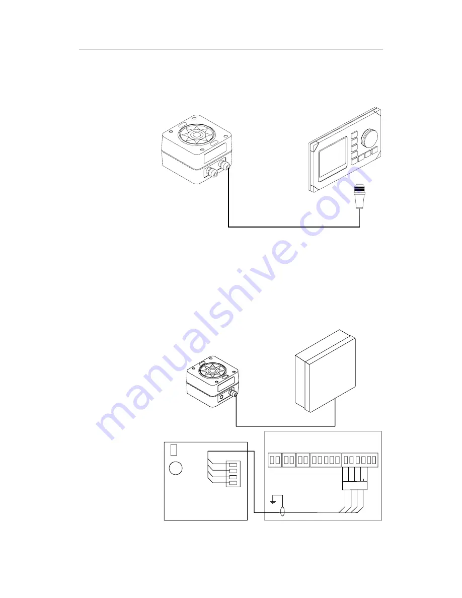
AP50
CONTROL
UNIT
RATE
COMPASS
Figure 2-32 RC25 Connection to AP50 Control Unit
•
Connect the Robnet connector to the AP50 Control Unit (or
GI51 or NI300X if installed).
•
Alternatively, if there is no free receptacle, cut the connector
from the cable and connect the wires in parallel with the
wires going from the distribution unit to the control unit.
Do
not connect the yellow and the green wires and ensure that
they do not connect with the terminal or chassis.
JD5X
DISTRIBUTION
UNIT
RATE
COMPASS
JD5X DISTRIBUTION UNIT
MAIN PCB
Robnet
V
sys+
V
sys
Gry
Pnk
PIN
K
GR
EY
PINK
GREY
WH
ITE
BRO
W
N
Bu
s
+
Bu
s
Bn Wht
WHITE
BROWN
TB15
RC25
RATE
COMPASS
Figure 2-33 Alternative Connection to JD5X Distribution Unit Robnet
Terminal
Summary of Contents for AP50
Page 2: ...INSTALLATION MANUAL SIMRAD AP50 Autopilot Plus System 20222410 B Sw 1 3 English...
Page 30: ...Installation 20222410 B 21 Figure 2 16 D9X Solid State Board component layout...
Page 34: ...Installation 20222410 B 25 Figure 2 21 External mode selection...
Page 48: ...Installation 20222410 B 39 Figure 2 36 S9 connection to JD5X...
Page 103: ...Simrad AP50 Autopilot 94 20222410 B This page is intentionally left blank...
Page 107: ...Simrad AP50 Autopilot 98 20222410 B This page is intentionally left blank...
Page 123: ...Simrad AP50 Autopilot 114 20222410 B This page is intentionally left blank...
Page 131: ...Simrad AP50 Autopilot 122 20222410 B This page is intentionally left blank...
Page 134: ...Simrad doc no 519103 F...
Page 135: ...Simrad doc no 519103 F...
Page 136: ...Simrad doc no 519107F...
Page 137: ...Simrad doc no 519107F...
Page 138: ...Simrad doc no 519107F...
Page 139: ...Simrad doc no 519107F...
Page 140: ......
Page 141: ......
Page 142: ...AP50 Installation manual Plus system EN Doc no 20222410 Rev B...


