11
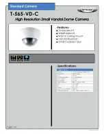
EXHAUST TUBE
INLET
TUBE
RUBBER
PLUG
INLET TUBE HOLES FACE
UPSTREAM OF AIR FLOW
Figure 10. Inlet Tube Installation
Table 2. Inlet Tube Selection
OVERALL DUCT
WIDTH
TUBE REQUIRED
TUBE TYPE
SUGGESTED TOTAL
LENGTH
12 inches (30 cm)
2098-9796
Hole
13 inches (33.02. cm)
½ inch (1.27 cm)
longer than duct width
13 inches (33.02 cm) to
23 inches (58 cm)
2098-9804
Hole
24 inches (60.96 cm)
½ inch (1.27 cm)
longer than duct width
23 inches (60 cm) to
46 inches (1.16 m)
2098-9797
Hole
49 inches (125.46 cm)
2 inches (5.8 cm)
longer than duct width
46 inches (1.16 m) to
71 inches (1.8 m)
2098-9798
Hole
73 inches (1.85 m)
2 inches (5.8 cm)
longer than duct width
71 inches (1.8 m) to
95 inches (2.4 m)
2098-9799
Hole
97 inches (2.45 m)
2 inches (5.8 cm)
longer than duct width
Housing Installation
5
.
Insert the inlet and exhaust tube receptors of the housing base into the two holes
previously cut in the duct.
6.
Using the four #8 self-tapping sheet metal screws provided in the accessory kit,
locate the four mounting hole locations that are marked inside on the duct
housing plastic (Detector Chamber marked “MTG”). Drill the four self-tapping
screws through the housing plastic and duct sheet metal to secure the duct
housing (no pre-drilling is required). Torque screws 10-12 inch-pounds.
Inlet Tube Installation (See Figures 9 and 10)
7.
Install the inlet tube by inserting the rubber plug end of the tube into the
upstream tube receptor located in the rear of the duct housing. The inlet tube
must be installed through the hole in the housing corner next to the smoke
port/air flow test holes. Place the tube retainer (supplied) over the inlet tube so
that the tab on the tube retainer goes into the slot on the inlet tube. Make sure
the tube retainer is in the proper orientation so that the holes in the inlet tube face
upstream into the airflow. The tab on the inlet tube retainer bracket indicates the
inlet hole side of the pipe.
Continued on next page
Installation,
Continued
Stand Alone Duct Detector
Installation (continued)
TAB
SEE NOTE 1
INLET TUBE RETAINER
BRACKET
Notes:
1.
The tab on the inlet tube retainer bracket indicates the inlet hole side of the
pipe.
2.
The inlet tube must be installed through the hole in the housing corner next to the
smoke port/air flow test holes.
SEE NOTE 2
firealarmresources.com
Summary of Contents for 4098-9687
Page 2: ...Blank Page firealarmresources com...
Page 4: ...Blank Page firealarmresources com...
Page 6: ...BLANK PAGE Blank Page firealarmresources com...
Page 25: ...Blank page firealarmresources com...
Page 26: ...Blank page firealarmresources com...