130
IT
ES
FR
BE
GB
RUS
RO
3.1
ELECTRONIC BOARD
Built according to Low Voltage direc-
tive 2006/95/CEE and powered at
230 Volt, via a transformer it sends
24 Volt power to the following compo-
nents: gas valve, safety thermostat,
heating probe, external temperature
pr obe (optional), wat er pr essur e
tr ansducer, air pr essur e switch,
room thermostat or “Remote Control
Logic”. An automatic and continual
modulation system permits the boiler
t o a d j u s t p o w e r t o t h e v a r i o u s
system or user needs. Electronic
components are guaranteed to ope-
rate in a temperature range from 0
to +60°C.
3.1.1
Malfunctions
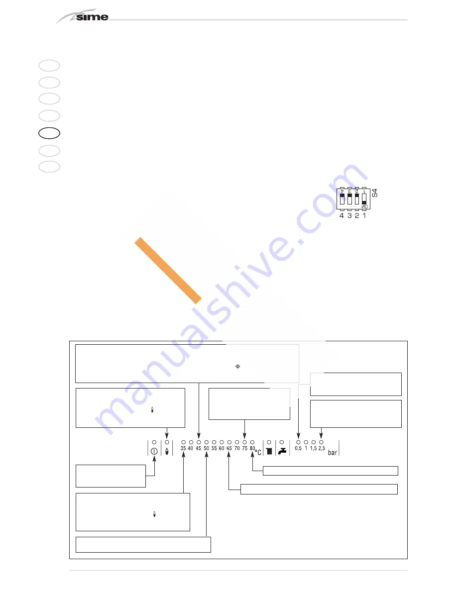
Boiler malfunctions or failures can be
indicated by a flashing temperature
LED as shown in fig 12.
3.1.2
Devices
The electronic board is equipped with
the following devices:
–
“HEATING POWER” TRIMMER
(10 fig. 13)
Adjusts maximum heating power. To
increase the value, rotate the trim-
mer clockwise, to reduce it, rotate
the trimmer counter-clockwise.
–
“IGNITION POWER” TRIMMER
(6 fig. 13)
Trimmer to vary the gas valve ignition
pressure level (STEP). According to
the type of gas the boiler is designed
for, the trimmer must be adjusted to
achieve a burner pressure of approxi-
mately 6.5 mm H
2
O for methane gas
and 9.5 mm H
2
O for propane gas
(G31). To increase pressure, rotate
the trimmer clockwise, to reduce it,
rotate the trimmer counter-clockwi-
se. The slow ignition pressure level
can be set during the first five
seconds after the burner is lit.
After setting the ignition pressure
level (STEP) according to the type of
gas, make sure that the heating gas
pressure is still the previously set
value.
–
“ANN. RIT.” CONNECTOR
(5 fig. 13)
The electronic board is program-
med, during heating, with a techni-
c a l b u r n e r d e l a y o f a b o u t 9 0
seconds that is performed both at
cold start and subsequent ignitions.
This is to prevent rapid ignitions and
shutdowns that could, in particular,
occur in systems with high load los-
ses. Each time the boiler restarts,
after the slow ignition, for about 1
minute it will run at minimum modu-
lation pressure before moving to
the set heating pressure.
The addition of a bridge will cancel
both the programmed technical
delay and the minimum pressure
operating period at ignition.
In this case, the time between shut-
d o w n a n d t h e n e x t i g n i t i o n w i l l
depend on a 5°C differential detec-
ted by the heating probe (SM).
–
DIP SWITCH
(13 fig. 13)
For correct module operations, the
dip switches must be positioned as
indicated below:
–
“Modureg Sel.” connector
(14 fig. 13)
The bridge must always be
connec-
ted
.
–
“Albatros” connector
(15 fig. 13)
The bridge must always be off. It is
only engaged in sequence/cascade
installations with several boilers.
WARNING: All the above operations
must be performed by authorised
personnel, otherwise the warranty
shall be invalidated.
3
CHARACTERISTICS
Flashing red led,
communication fault
with “Logica Remote Control”
Green led off if
power is cut-off
Blinking red air pressure switch fault led
Flashing red led, water
pressure is too low (*)
Flashing red led, heating sensor fault (SM)
Flashing red led,
plant safety
valve tripped (*)
Red led on, ignition blocked:
rotate selector CR/OFF/EST/INV/RESET
to release position (
)
to restore operation
Flashing red led, safety stat tripped.
Rotate selector CR/OFF/EST/INV/RESET
to release position (
)
to restore operation
(*) When all 0.5 to 2.5 bar leds are off, check the water pressure transducer
connection.
WARNING: the operation of plants with open vessels is guaranteed only for
static pressures above 0.7 bar.
On model “100 BFR” continuous operation can be guaranteed, even for pres-
sure reductions > 4 bars, by activating jumpers X4 e X25 (fig. 13) only and
electrically disconnecting the connector from the water pressure transducer.
The operating pressure can be measured using the pressure gauge installed
in the plant.
Fig. 12
Flashing red led, flame detection circuit fault
Blinking red fan fault led. 30 minutes after the fan turns off, the board attempts to
restart it. To identify where the fault occurred in sequence/cascade installations, turn
the CR/OFF/INV/RELEASE selector on each module to the (
) position and check
where the red fault led blinks.


