Sim2 Grand Cinema RTX 55H User And Installation Manual Download Page 20

18

F1/F2 KEYS

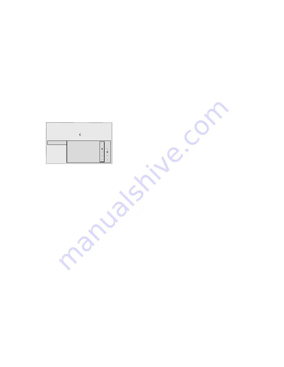
This allows to assign different functions to the remote control
keys, named F1 and F2.
The window is made of 4 options 

(Fig.17)

, once for each line

and by two columns showing the F1-F2 keys. The choice
between F1 and F2 is made by the 

 and 

 keys of the remo-

te control; the function given to F1 and F2 is chosen with the 

and 

 keys.

The function delivered by the key is memorized by the
intersection on the line and column.
In the following window are described the 4 options.

Source list
F1/F2 keys
Source info
OSD Backgroung

OSD Position
OSD Timeout

Language

Menu

English

Magnification
Blank
Colour temperature
Gamma correction

F1 F2

Fig.17

Magnification

Allows you to select the area to be viewed and then magnify
the projected image. The degree of enlargement is selected in
Zoom mode (identified by a magnifying glass in the centre of
the image) using the 

 and 

  keys. The area of the picture to

be enlarged is selected  in Pan mode (symbol in the centre of
the picture) using the  

 and 

   arrow keys. You can

toggle between Zoom and Pan mode by pressing the  F1/F2
key on the remote control.

BLANK

Blanks the active video signal producing a completely black
screen. Once pressed the key an indication of a few seconds
on the OSD will confirm its activation. A click of any other key
of the remote control allows to restore the previous settings.

Color temperature

The following click of the key (F1 or F2) allows to choose between
the different color temperatures available. High, Mid, Low, User.

Gamma correction

The following click of the key (F1 or F2) allows to choose
between the different gamma curves available.

SOURCE INFORMATION

When active (YES) each source change will show the information
related to the signal. If not active (NO) there will be no information
on the selected source.

OSD BACKGROUND

Determines the type of background for the On Screen Display.

OSD TIMEOUT

Use this adjustment to set the display time after which the On
Screen Display will disappear.

OSD POSITION

Allows the On Screen Display to be positioned in a particular
area of the projected image. The OSD can be positioned using
the arrow keys for fine adjustments or keys 1...9 on the remote
control to select one of 9 preset positions.

Summary of Contents for Grand Cinema RTX 55H

Page 1: ...cod 46 0360 200 RTX 55H User and Installation Manual Look Forward...

Page 2: ...us Navigates menu pages MEMORIES Activates Memories menu INFO Displays the selected source information and the projector status VCR Improves the video recorder signals quality ASPECT Selects image Asp...

Page 3: ...1 1 INTRODUCTION Congratulations on your choice of the SIM2 Grand Cinema RTX 55H system O N D I G I O P T I C I M A G E P R O C E S S O R O F F...

Page 4: ...capabilities of the DigiOptic Image Processor with the high fidelity reproduction of the DLP technology Display by linking the two units via a fibre optic cable The DigiOptic Image Processor which sh...

Page 5: ...rent from that to which the receiver is connected Consult the dealer or an experienced radio Tv technician for help For customers in Canada This Class B digital apparatus complies with Canadian ICES 0...

Page 6: ...possible to the wall electrical socket outlet Do not tread on the power cables make sure that they are not tangled or pulled do not expose the power cables to heat sources make sure that the power cab...

Page 7: ...ace is stable and that the unit has sufficient space around it for ventilation purposes at least 3 cm The unit is connected to the mains via an external power supply unit with an output of 7 Vdc the u...

Page 8: ...ck that the connectors are correctly inserted Use the cable clamps on the rear panel of the Display to protect the connectors from traction and leverage Fibra Ferrule Protective cap Separation point C...

Page 9: ...VIDEO Although other types of signals are preferable since they allow better picture quality this is still the most common type of output and nearly all television receivers video recorders DVD playe...

Page 10: ...of between 32 and 80 kHz and a vertical frequency V sync of between 48 and 100 Hz Image resolution can vary between 640x480 and 1600x1200 pixels VGA SVGA XGA SXGA UXGA DVI D 11 If your source is equi...

Page 11: ...9 Fig 6...

Page 12: ...o LEDs green and blue on the front panel of the DigiOptic Image Processor a blue and green LEDS on the rear of the Display Significant status signals are given in Table 3 4 SWITCHING ON AND OFF Off In...

Page 13: ...ing the power cord cable to re boost the RTX system it is necessary to shut down the DigiOptic Image Processor and repeat the power on procedure described in point 1 and 2 5 KEYPAD The keypad on the b...

Page 14: ...o select an input scroll the list with the and keys until the desired input is highlighted then press Display of the input selection menu is terminated by pressing the ESC key or when the time allowed...

Page 15: ...ypad or the MENU or MENU key on the re mote control The main menu is divided into four windows PICTURE IMAGE SETUP and MENU in which the various adjustments are grouped according to the frequency of u...

Page 16: ...defined SHARPNESS MODE This allows you to select the type of processing associated with sharpness adjustment In the case of a progressive or interlaced video signal VIDEO mode is advisable with PC gr...

Page 17: ...9 screen of the Display PIXELTOPIXEL this aspect displays the image as it is input without adapting it to the screen The image is projected in the centre of the screen and if its horizontal and or ver...

Page 18: ...e equidistant vertical bands or instability and lack of sharpness on the narrow vertical lines it may help to prompt the system to repeat the input signal analysis and determination of the best parame...

Page 19: ...o rename the source in use This will make it easier to remember the source connected to a specific input You can use up to 12 alphanumeric letters to name the source for more details check the Insert...

Page 20: ...u can toggle between Zoom and Pan mode by pressing the F1 F2 key on the remote control BLANK Blanks the active video signal producing a completely black screen Once pressed the key an indication of a...

Page 21: ...d keys to move to line 1 and then open the pull down menu by pressing the key Fig 19 Then select the option Save current settings To confirm that the operation has been completed successfully the mess...

Page 22: ...ore the original values to a previously modified Memory select the line corresponding to the Memory in question and open the pull down menu key Then select the line Initial settings saved in Memory 1...

Page 23: ...er Clean the filter by shaking it vigorously to remove the dust or usin a jet of compressed air now refit the filter to the rear of the grille Fig C and secure it by pressing on the adhesive stickers...

Page 24: ...c image adjustment function by pressing the AUTO key on the remote control or the Display keypad Adjust the horizontal or vertical position of the projected image using the IMAGE ADJUSTMENTS POSITION...

Page 25: ...00 3 3 Transport IEC 68 2 31 IEC 68 2 32 TECHNICAL SPECIFICATIONS DIGIOPTIC IMAGE PROCESSOR ELECTRICAL Input signals 2 COMPOSITE VIDEO CVBS RCA type connectors gold plated 1 0 Vpp 75 negative synchron...

Page 26: ...gth 2 m Power supply 100 to 240 VAC tolerance 10 frequency from 48 to 62 Hz Consumption 30W max Dimensions 483 x 55 x 200 mm WxHxD compatible with 19 rack Weight approx 2 5 kg Operating Temperature 10...

Page 27: ...NSIONS DISPLAY DIGIOPTIC IMAGE PROCESSOR Unit of measure mm Scale 1 5 Unit of measure mm Scale 1 20 RTX 55 H 1494 1218 1188 250 425 1228 685 440 289 57 D I G I O P T I C I M A G E P R O C E S S O R O...

Page 28: ...rightness Contrast Color Tint Sharpness Sharpness Mode Brightness Contrast Color Sharpness Filter Cinema Mode Video Type Noise reduction Noise reduction Video S Video PAL SECAM Aspect Color Temperatur...

Page 29: ...MPONENT RGBS 1 VIDEO 1 2 3 4 S VIDEO 4 5 6 7 8 9 10 GRAPHICS RGB 11 DVI D VIDEO 2 S VIDEO 3 GRAPH RGB 9 GRAPH RGB 10 DVI D 11 COMP RGB 5 COMP RGB 6 COMP RGB 6 COMP RGB 7 COMP RGB 8 VIDEO 1 S VIDEO 4 1...

Page 30: ...TION 23 A Technical specification 23 B Dimensions 25 C On screen menu layout 26 1 INTRODUCTION 1 2 IMPORTANT SAFETY INSTRUCTIONS 3 3 INSTALLATION 5 Connecting the two units 5 Connecting the video sour...

Page 31: ...im2 com e mail info sim2 it SIM2 USA Inc 10108 USA Today Way 33025 Miramar FL USA Phone 1 954 4422999 Fax 1 954 4422998 www sim2usa com e mail sales sim2usa com SIM2 Deutschland GmbH Gewerbepark 17 D...

Reviews: