


1-7
16
Troubleshooting
Before contacting technical support, refer to this section.
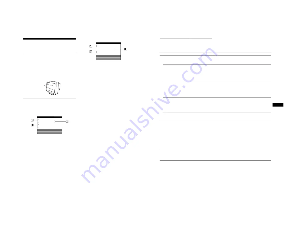
If thin lines appear on your screen
(damper wires)
The lines you are experiencing on your screen are normal for the
Trinitron monitor and are not a malfunction. These are shadows
from the damper wires used to stabilize the aperture grille and are
most noticeable when the screen’s background is light (usually
white). The aperture grille is the essential element that makes a
Trinitron picture tube unique by allowing more light to reach the
screen, resulting in a brighter, more detailed picture.
On-screen messages
If there is something wrong with the input signal, one of the
following messages appears on the screen.
If NO INPUT SIGNAL appears on the screen
If OUT OF SCAN RANGE appears on the screen
For more information, see “Trouble symptoms and remedies” on
page 17.
1
The selected connector
This message shows the currently selected connector
(INPUT 1 or INPUT 2).
2
The input signal condition
NO INPUT SINGAL
This indicates that no signal is input, or that no signal is input
from the selected connector.
3
The remedies
One or more of the following messages may appear on the
screen.
• If ACTIVATE USING PC appears on the screen, try
pressing any key on the computer, and confirm that your
computer’s graphic board is completely seated in the
correct bus slot.
• If CHECK INPUT SELECTOR appears on the screen, try
changing the input signal (page 7).
• If CHECK SIGNAL CABLE appears on the screen, check
that the monitor is correctly connected to the computer
(page 6).
Damper wires
MON I TOR
I S WORK I NG
I NPUT
1 :
NO
I NPUT
S I GNA L
ACT I VA T E US I NG PC
CHECK
I NPUT SE L ECT R
O
CHECK S I GNA L CAB L E
WH I T E
RED
GREEN
B L UE
I NFORMA T I ON
1
The selected connector and the frequencies of the
current input signal
This message shows the currently selected connector
(INPUT 1 or INPUT 2). If the monitor recognizes the
frequencies of the current input signal, the horizontal and
vertical frequencies are also displayed.
2
The input signal condition
OUT OF SCAN RANGE
This indicates that the input signal is not supported by the
monitor’s specifications.
3
The remedies
CHANGE SIGNAL TIMING appears on the screen. If you
are replacing an old monitor with this monitor, reconnect the
old monitor. Then adjust the computer’s graphic board to that
the horizontal frequency is between 30 - 121 kHz, and the
vertical frequency is between 48 - 160 Hz.
MON I TOR
I S WORK I NG
I NPUT
1 : 1 3 0 . 0 k H z /
H
5
7
OU T OF SCAN RANGE
CHANGE S I GNA L
T I M I NG
WH I T E
RED
GREEN
B L UE
I NFORMA T I ON
z
17
GB
Trouble symptoms and remedies
If the problem is caused by the connected computer or other equipment, please refer to the connected equipment’s instruction manual.
Use the self-diagnosis function (page 19) if the following recommendations do not resolve the problem.
Symptom
Check these items
No picture
If the
1
(power) indicator is not lit
• Check that the power cord is properly connected.
• Check that the
1
(power) switch is in the “on” position.
If the NO INPUT SIGNAL message
appears on the screen, or if the
1
(power) indicator is either orange or
alternating between green and
orange
• Check that the
t
switch setting is correct (page 7).
• Check that the HD15 video input connector’s pins are not bent or pushed in.
x
Problems caused by the connected computer or other equipment
• The computer is in power saving mode. Try pressing any key on the computer keyboard.
• Check that the computer’s power is “on.”
• Check that the graphic board is completely seated in the proper bus slot.
If the NO INPUT SIGNAL and
CHECK SIGNAL CABLE message
appear on the screen, or if the
1
(power) indicator is either orange or
alternating between green and
orange
• Check that the video signal cable is properly connected and all plugs are firmly seated in
their sockets (page 6).
• Check that the HD15 video input connector’s pins are not bent or pushed in.
• Check that the
t
switch setting is correct (page 7).
x
Problems caused by the connected computer or other equipment
• Check that the graphic board is completely seated in the proper bus slot.
If the OUT OF SCAN RANGE
message appears on the screen
x
Problems caused by the connected computer or other equipment
• Check that the video frequency range is within that specified for the monitor. If you
replaced an old monitor with this monitor, reconnect the old monitor and adjust the
frequency range to the following.
Horizontal: 30 – 121 kHz
Vertical: 48 – 160 Hz
If no message is displayed and the
1
(power) indicator is green or flashing
orange
• Use the Self-diagnosis function (page 19).
Picture flickers, bounces,
oscillates, or is scrambled
• Isolate and eliminate any potential sources of electric or magnetic fields such as other
monitors, laser printers, electric fans, fluorescent lighting, or televisions.
• Move the monitor away from power lines or place a magnetic shield near the monitor.
• Try plugging the monitor into a different AC outlet, preferably on a different circuit.
• Try turning the monitor 90
°
to the left or right.
x
Problems caused by the connected computer or other equipment
• Check your graphics board manual for the proper monitor setting.
• Confirm that the graphics mode and the frequency of the input signal are supported by this
monitor. Even if the frequency is within the proper range, some video boards may have a
sync pulse that is too narrow for the monitor to sync correctly.
• Adjust the computer’s refresh rate (vertical frequency) to obtain the best possible picture.
Picture is fuzzy
• Adjust the brightness and contrast (page 9).
• Degauss the monitor* (page 13).
• If CANCEL MOIRE is ON, the picture may become fuzzy. Decrease the moire
cancellation effect or set CANCEL MOIRE to OFF (page 11).


