


18
Additional Information
Warning Messages
If there is something wrong with the input signal, one of the
following messages appears.
The message disappears after about 30 seconds.
Additional Information
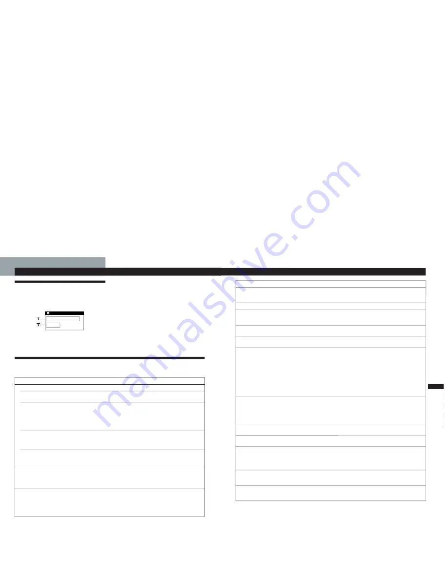
1
The input signal condition
“OUT OF SCAN RANGE”
indicates that the input signal
is not supported by the monitor’s specifications.
“NO INPUT SIGNAL”
indicates that no signal is input, or
the input signal from the selected input connector is not
received.
2
The selected input connector
Indicates which input connector is receiving the wrong
signal. If there is something wrong with the signal from
both input connectors, “1” (HD15) and “2” (13W3) are
displayed alternately.
To solve these problems, see “Troubleshooting” below.
Troubleshooting
This section may help you isolate the cause of a problem and as a result, eliminate the need to contact technical support.
Symptom
Check these items
No picture
If the
u
indicator is not lit
If the “NO INPUT SIGNAL”
message appears on the
screen, or if the
u
indicator is
either orange or alternating
green and orange
If the “OUT OF SCAN
RANGE” message appears on
the screen
If no message is displayed
and the
u
indicator is green
or flashing orange
Picture is scrambled
Color is not uniform
• Check that the power cord is properly connected.
• Check that the
u
(power) switch is in the “on” position.
• Try pressing any key on the computer keyboard.
• Check that your computer power switch is in the “on” position.
• Check that the input select setting is correct.
• Check that the video signal cable is properly connected and all plugs are firmly seated
in their sockets.
• Ensure that no pins are bent or pushed in the HD15 or 13W3 video input connector.
• Check that the video frequency range is within that specified for the monitor.
(Horizontal: 30 – 96 kHz, Vertical: 48 – 160 Hz)
Refer to your computer’s instruction manual to adjust the video frequency range.
• If you are using a video signal cable adapter, check that it is correct.
• See “Self-diagnosis Function” (page 20).
• Check your graphics board manual for the proper monitor setting.
• Check this manual and confirm that the graphics mode and the frequency you are
trying to operate at is supported. Even if the frequency is within the proper range,
some video boards may have a sync pulse that is too narrow for the monitor to sync
correctly.
• Degauss the monitor (page 13).
If you place equipment which generates a magnetic field, such as a loudspeaker, near
the monitor, or you change the direction of the monitor, color may lose uniformity.
The degauss function demagnetizes the metal frame of the CRT to obtain a neutral
field for uniform color reproduction. If a second degauss cycle is needed, allow a
minimum interval of 20 minutes for the best result.
INFORMATION
OUT OF SCAN RANGE
INPUT : 1
19
Getting Started
F
EN
D
ES
I
Additional Information
Symptom
Check these items
You cannot adjust the
monitor with the buttons on
the front panel
White does not look white
Screen image is not centered
or sized properly
Edges of the image are
curved
White lines show red or blue
shadows at edges
Picture is fuzzy
Picture bounces or has wavy
oscillations
Picture is flickering
Picture appears to be
ghosting
Wavy or elliptical (moire)
pattern is visible
Two fine horizontal lines
(wires) are visible
Hum is heard right after the
power is turned on
• If the control lock function is set to on, set it to off using the OPTION OSD (page 15).
• Adjust the color temperature (page 12).
• Adjust the size or centering (pages 9 – 10).
• Some video modes do not fill the screen to the edges. This problem tends to occur with
certain video boards.
• Adjust the geometry (pages 10 – 11).
• Adjust the convergence (pages 12 – 13).
• Adjust the contrast and brightness (page 8).
• Degauss the monitor (page 13).
If you place equipment which generates a magnetic field, such as a loudspeaker, near
the monitor, or you change the direction of the monitor, color may lose uniformity.
The degauss function demagnetizes the metal frame of the CRT to obtain a neutral
field for uniform color reproduction. If a second degauss cycle is needed, allow a
minimum interval of 20 minutes for the best result.
• If red or blue shadows appear along the edges of images, adjust the convergence
(pages 12 – 13).
• If the moire is cancelled, the picture may become fuzzy. Decrease the moire
cancellation effect (pages 12 – 13).
• Isolate and eliminate any potential sources of electric or magnetic fields. Common
causes for this symptom are electric fans, fluorescent lighting or laser printers.
• If you have another monitor close to this monitor, increase the distance between them
to reduce the interference.
• Try plugging the monitor into a different AC outlet, preferably on a different circuit.
• Try the monitor on a different computer in a different room.
• Set the refresh rate on the computer to obtain the best possible picture by referring to
the computer’s manual.
• Eliminate the use of video cable extensions and/or video switch boxes if this symptom
occurs. Excessive cable length or a weak connection can produce this symptom.
• Cancel the moire (pages 12 – 13).
The moire may be modified depending on the connected computer.
• Due to the relationship between resolution, monitor dot pitch and the pitch of some
image patterns, certain screen backgrounds sometimes show moire. Change your
desktop pattern.
• These wires stabilize the vertically striped aperture grille (page 17). This aperture grille
allows more light to pass through to the screen giving the Trinitron CRT more color
and brightness.
• When the power is turned on, the auto-degauss cycle is activated. While the auto-
degauss cycle is activated (2 seconds), a hum may be heard. The same hum is heard
when the monitor is manually degaussed. This is not a malfunction.
1-6


