2.2 Installing motherboard components
Chapter 2: Setting up
13
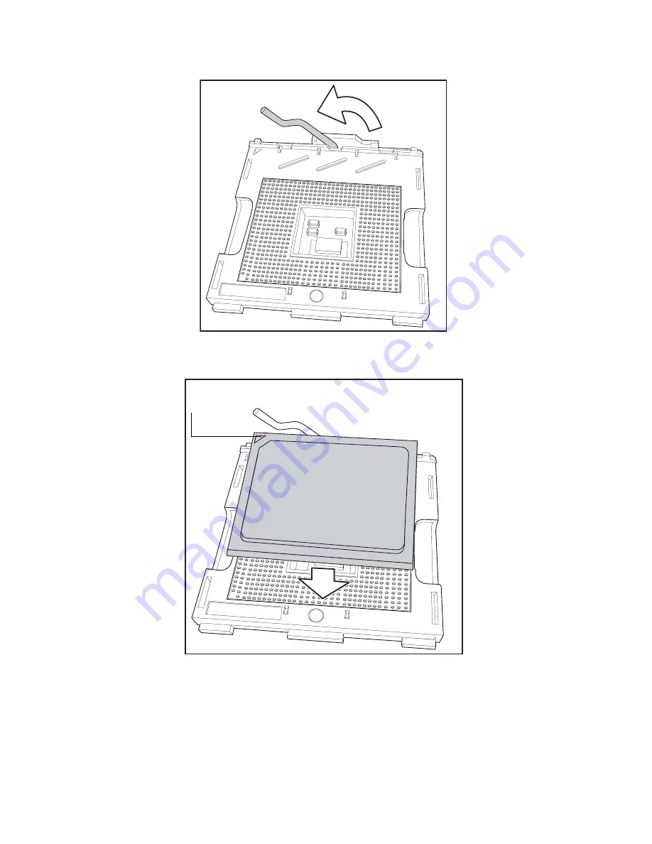
4. Lift the CPU locking lever as shown below.
5. Place the CPU in the CPU socket, ensuring that pin 1 is
located as shown in the following illustration.
6. Press the CPU locking lever back down to secure the
CPU in the socket.
7. Repeat steps three to six for the second CPU.
8. Apply thermal grease to the top of the CPUs and place
the CPU heatsinks on the CPUs.
pin 1
Summary of Contents for Transport GX21 B5350
Page 32: ...2 4 Rack mounting 26 Chapter 2 Setting up...
Page 49: ...Appendix 43 IDE channel submenus You can use this screen to change IDE Configuration Set tings...
Page 55: ...Appendix 49 Hardware monitor You can use this screen to change critical system settings...
Page 67: ...Appendix 61 Boot menu You can use this screen to set boot up options...
Page 70: ...64 Appendix...


