8.6.2 Mounting the Head Unit
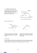
Head unit terminal
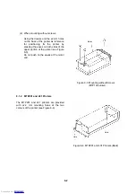
(1) Move the head carrier to a position that
permits easy replacement (see Figure
8-15).
Solder-plated face
(2) Insert the head unit terminal between the
platen and the guide pin and head feeding
screw with the soldered surface of the head
unit terminal upwards (see Figure 8-15).
Holding the solder-plated face upward,
insert the head unit terminal so that it
passes in front of the platen and under the
guide pin and the head feed screw.
Guide pin
Platen
Head feed screw
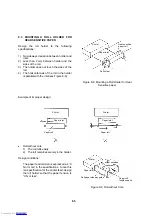
(3) After inserting the head unit terminal,
arrange the components as shown in
Figure 8-16.
Then, rotate the head portion of the unit by
90
°
into the position shown in Figure 8-17.
Figure 8-15 Inserting the Head Unit Terminal
Head
90
°
Slit
Head carrier frame
Figure 8-16 Rotating the Head Portion of the
Unit
8-10
Downloaded from
Downloaded from
Downloaded from
Downloaded from
Downloaded from
Downloaded from
Downloaded from
Downloaded from
Downloaded from
Downloaded from
Downloaded from
Downloaded from
Downloaded from
Downloaded from
Downloaded from
Downloaded from
Downloaded from
Downloaded from
Downloaded from
Downloaded from
Downloaded from
Downloaded from
Downloaded from
Downloaded from
Downloaded from
Downloaded from
Downloaded from
Downloaded from
Downloaded from
Downloaded from
Downloaded from
Downloaded from
Downloaded from
Downloaded from
Downloaded from
Downloaded from
Downloaded from
Downloaded from
Downloaded from
Downloaded from
Downloaded from
Downloaded from
Downloaded from
Downloaded from
Downloaded from
Downloaded from
Downloaded from
Downloaded from
Downloaded from
Downloaded from
Downloaded from


