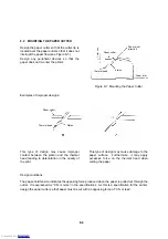
8.2 MOUNTING THE PAPER CUTTER
Paper eject
direction
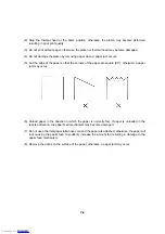
Design the paper cutter so that the cutter tip is
located over the paper outlet so that it does not
interrupt the paper flow (see Figure 8-7).
1mm min.
Paper cutter
Design any peripheral devices so that the
paper does not re-enter the printer.
platen
Thermal head
Paper inlet
Figure 8-7 Mounting the Paper Cutter
Examples of improper designs:
Paper cutter
Thermal head
Platen
This type of design may cause improper
contact between the platen and the thermal
head leading to deterioration in the quality of
the print.
This type of design may cause damage to the
paper surface. Furthermore, it may apply
excessive force on the thermal head when
cutting the paper.
Design conditions:
The paper-hold tension indicates the opposing force produced when the paper is pulled out through the
outlet. It is expressed as “X N or more” in the specifications. As this is a specification for the printer,
design the paper cutter so that paper must be cut with an opposing force of “X N or less”.
8-4
Downloaded from
Downloaded from
Downloaded from
Downloaded from
Downloaded from
Downloaded from
Downloaded from
Downloaded from
Downloaded from
Downloaded from
Downloaded from
Downloaded from
Downloaded from
Downloaded from
Downloaded from
Downloaded from
Downloaded from
Downloaded from
Downloaded from
Downloaded from
Downloaded from
Downloaded from
Downloaded from
Downloaded from
Downloaded from
Downloaded from
Downloaded from
Downloaded from
Downloaded from
Downloaded from
Downloaded from
Downloaded from
Downloaded from
Downloaded from
Downloaded from
Downloaded from
Downloaded from
Downloaded from
Downloaded from
Downloaded from
Downloaded from
Downloaded from
Downloaded from
Downloaded from
Downloaded from

