SIGMAKOKI OptoSigma PGC-04-U Manual Download Page 44

SC40401-K10-15002


1st 


44 

Copyright 2015, SIGMAKOKI Co.,Ltd. 


4-1-6-2 E

1 command


(Arc interpolation movement command 1) 

(1) Function 

This command indicates a designation of center point and degree of ended point in order to operate the 

arc movement 

(2) Example


E

1, axis1,axis2,d,c1,c2,ae 

axis1, axis2

1

4  means  to  designate  the  number  of  axis  to  operate  arc  interpolation 

movement.  Same  number  of  axis  or  unconnect  is  prohibited.  Axis1 

represents X axis and axis2 represents Y axis. 


d

0 or 1   

0 is CW rotation(Clockwise). 1 is CCW rotation (Counterclockwise). 


c

Center point coordinate  (c1 axis1 setting value

c2 axis2 setting value) 

(unit of setting 0.01

µ

m unit) 

ae

Degree of ended point (deg)    (Setting range

integer of 0°<ae

360° The other degree 

than mentioned is NG.) 


E

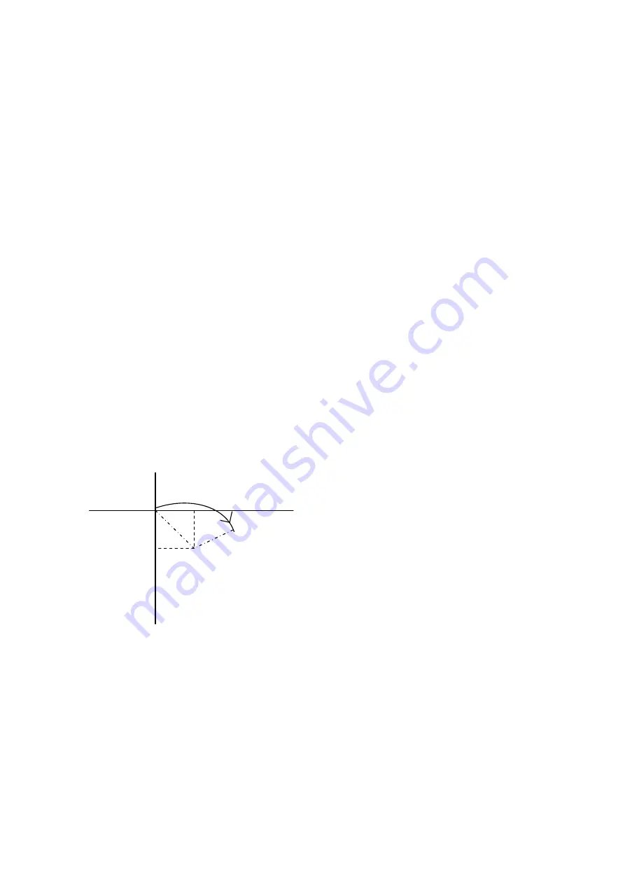
1,3,4,0,5000,-5000,90 

A center point coordinate is based on a relative coordinate of the current 

position  (0.05mm,-0.05mm)  and  move  stages  of  axis  No3

axis  No4 

90°from current position to degree of ended point position clockwise. 


0.05mm 

-0.05mm 

90

°


Axis 3 

Axis4 

Summary of Contents for OptoSigma PGC-04-U

Page 1: ...SC40401 K10 15002A 2nd 1 Copyright 2018 SIGMAKOKI Co Ltd Pulse Generating Controller PGC 04 U...

Page 2: ...he information contained in these materials including product data diagrams charts programs and algorithm please be sure to evaluate all information and products SIGMAKOKI CO LTD assumes no responsibi...

Page 3: ...of drivers and servopack 16 2 5 Connection between PGC 04 U and motoried stage Driver 21 2 6 Connection between driver and motorized stage at the time of standard cable use 22 2 7 Interface with PC 22...

Page 4: ...triangle indicate warnings and cautions The exact nature of the warning or caution is indicated by the symbol inside the symbol at left indicates risk of electrocution Symbols enclosed in a circle mar...

Page 5: ...n provided by the equipment may be impaired WARNING Do not use this product in the presence of flammable gas explosives or corrosive substances in areas exposed to high levels of moisture or humidity...

Page 6: ...u can set it by sample software Sample software are available for download our website WEB http www global optosigma com en_jp software sample_en html 1 2 Overview This controller below PGC 04 U is a...

Page 7: ...I O control Please interface with 10120 3000PE by 3M Company USB Cable LAN Cable 1 Control from PC 1 In case of connection between PC and PGC 04 U directry please use cross cable and in case of connec...

Page 8: ...rious User s manuals 6 I O Connector It interfaces with input output signal for external devices 7 FG Terminal It is Terminal for Frame Ground Please connect to Earth in the actual environment 8 Power...

Page 9: ...When removing the top cover a power supply Plese carry it out in a state of power supply OFF by all means Replace jumper pin of following Fig 2 1 in the AM side _step motor and AC servo motor side fro...

Page 10: ...output 4 PM 5 CLR ERC Clear signal output AC_SRV and ALPHA setting 6 Servo_ON STEP4 Servo_ON signal output AC_SRV ALPHAsetting STEP4 signal output STEPNG setting 7 P_Reset STEP3 P_Reset signal output...

Page 11: ...25 GND GND 26 GND 1 About the TIM Z_P signal refer to 2 1 Connection setup various drivers the SERVO PACK It becomes the line driver tray setting in AM side setting photo coupler tray setting in SP s...

Page 12: ...c Corporation When you connect with the AC servo pack SGDV series please connect using standard cable PGC ACS or please connect the following connection after reference When use an AC servo pack AM si...

Page 13: ...OrientalMotor When you connect with the _STEP AR series please connect using standard cable PGC ARD or please connect the following connection after reference When use an _STEP AM side setting please...

Page 14: ...e connect using standard cable PGC S0514ZU or please connect the following connection after reference When use an MC S0514ZU SP side setting please while referring to a 2 1 clause When use an MC S0514...

Page 15: ...ORG NEAR please use standard cable option or connect according to the following circuit diagram Please set input logic polarity NORMAL OPEN NORMAL CLOSE of each sensor by a memory switch Sensor 1 12 a...

Page 16: ...wnload Sigma Win from YASKAWA Electric Corporation HP http www e mechatronics com download tool servo sgmwinpls index html 2 Connect PC and Servopack Please connect a PC in which Sigma Win is installe...

Page 17: ...ity please start Sigma Win When connecting for the first time please confirm the connection of a servo pack in Search When the connection is confirmed connected servo pack and servomotor are indicated...

Page 18: ...AKOKI Co Ltd Please set the following parameter in parameter edit Pn002 Default 0000H Change 0100H Uses absolute encoder as an incremental encoder Pn200 Default 0000H Change 2001H Input filter 4Mpps a...

Page 19: ...tio 1 1 please calculate as follows and input Screw lead p mm The amount of transfer per 1 pulse u um Electronic Gear Ratio Denominator p 1000 u Please make electronic gear ratio an integer example Wh...

Page 20: ...l _STEP AR series product made in OrientalMotor setting 1 ARD K _STEP driver setting The setting is changed by the front switch of driver Resolution Please set resolution per motor 1 round by SW1 No 3...

Page 21: ...of each driver Please set memory switch axis 9 12 PLS_RATE according to the above Pulse input system Pulse output of PGC 04 U is 2pulse system Please set it as 2 pulsed system by each driver 2 5 Conn...

Page 22: ...In this case please set the memory switch Interface to USB Default setting is USB PGC 04 U performs USB serial conversion using FT232 by FTDI For PC control driver should be installed in PC For inform...

Page 23: ...matic driver will start If unconnected to the Internet from FTDI s website on a PC connected to the Internet please go to download the driver VCP Drivers Then move the driver that download to PC to co...

Page 24: ...ch contents list and detailed settings 3 2 1 General No Memory Switch contents Setting Range Select items Default Value 1 SPD SEL 1 4 1 2 SPD 1 S 1 999999999 10000 3 SPD 1 F 1 999999999 100000 4 SPD 1...

Page 25: ...etting Select Logic Voltage level for I O output signal Select item ACT HIGH Lo level Active High normally ACT LOW Hi level Active low normally 3 2 2 INTERFACE No Memory Switch contents Setting Range...

Page 26: ...PLS_RATE3 1 1000000 1000 12 PLS_RATE4 1 1000000 1000 13 MOVE1 POS NEG POS 14 MOVE2 POS NEG POS 15 MOVE3 POS NEG POS 16 MOVE4 POS NEG POS 17 ORG1 SEL OFF MINI CENTER ORGS NORM ZPM ZPP MINI 18 ORG2 SEL...

Page 27: ...20 25 40 50 80 100 125 200 250 9 12 PLS_RATE1 4 Pulse Rate setting 1 4axes Set the travel distance per 1 pulse for each axis Otherwise it is not able to position correctly Setting Unit 0 1nm 1 Setting...

Page 28: ...xitation ON or OFF for each axis at at Emergency STOP Select item ON Exitation ON OFF Exitation OFF 29 32 DRIVER1 4 Connection Driver setting Select connection Driver Select item STEPNG 5 phase Steppi...

Page 29: ...axis can be individually set Please select the optimum value according to the software In case of when PGO Z pulse is used as an Origin sensor ORG5 or ORG6 Origin sensor is not in need at stage since...

Page 30: ...W limit sensor ORG reset speed F Move 0 5mm ORG reset speed M Detect CW limit sensor ORG reset speed M Detect CCW limit sensor ORG reset speed M ORG reset speed S Move 0 5mm ORG reset speed S Detect C...

Page 31: ...n case of no ORG sensor stage stop at CCW CW sensor position 5 ORG4 for 4 sensor LS SD ORG use 5 1 In case that NEAR ORG sensor is on the inside of CW CCW sensor Detect ORG sensor ORG sensor ORG reset...

Page 32: ...2 In case that after detect NEAR ORG sensor stage move toward CW direction and then can not detect ORG sensor in case of no ORG sensor stage stop at CW CCW sensor position 6 ORG5 for 3 sensor use LS...

Page 33: ...RG6 for 3 sensor use LS ORG Z phase ORG sensor Z phase ORG reset speed F Detect CW limit sensor Move to offset position Detect ORG sensor Z phase CW CCW sensor ORG reset speed M ORG reset speed S ORG...

Page 34: ...1 4axis Select limit sensor detecting level Input logic level for each axis Select item NM Open Normally switch ON by detecting limit sensor from SW OFF condition NM Close Normally switch OFF by dete...

Page 35: ...50000 15 ORG3 SPD M 1 999999999 250000 16 ORG4 SPD M 1 999999999 250000 17 ACC CNT1 LINEAR S CURVE LINEAR 18 ACC CNT2 LINEAR S CURVE LINEAR 19 ACC CNT3 LINEAR S CURVE LINEAR 20 ACC CNT4 LINEAR S CURVE...

Page 36: ...e 3 1 Sample software SGSample 3 Please click Set tab according to Fig 3 1 and select LAN in interface of communication setting Fig 3 2 Fig 3 2 Communication setting screen 4 Please open communication...

Page 37: ...by clicking Settings on Communication settings Figure 3 3 6 Click OK after setting IP address on Figure 3 4 LAN settings in accordance with PC condition Fig 3 3 Communication settings Fig 3 4 LAN sett...

Page 38: ...p1 p3 p4 Parameter of 2 axis is abbreviated p1 p2 Parameter of 3 and 4 axis is abbreviated Capital or lower case characters can be used Example h and H are both valid for the Home command Backspace i...

Page 39: ...ttings of linear interpolation movement Linear interpolation Move at minimum speed S J Jog command Move by minimum speed S L Stop Stop or reduce speed R Set electronic logical origin Set the electroni...

Page 40: ...217727 In case of the over number NG will be returned and stage will not move Note The above limitation is conflicted when a high microstep is set 2 Example M 100000 20000 30000 means to move from cur...

Page 41: ...t will be effective only with respect to the axis of the move Busy state Therefore it becomes NG If you have issues a command to the axis of the Ready state In addition the specified position coordina...

Page 42: ...cceleration and Deceleration pattern Trapezoidal shape or S shape is same pulse speed and travel per pulse are different However the speed when operates the arc interpolation movement is minimum speed...

Page 43: ...unconnect is prohibited Axis 1 represents X axis and axis 2 represents Y axis d 0 or 1 0 is CW rotation Clockwise 1 is CCW rotation Counterclockwise e Ended point coordinate e1 axi1 setting value e2...

Page 44: ...ect is prohibited Axis1 represents X axis and axis2 represents Y axis d 0 or 1 0 is CW rotation Clockwise 1 is CCW rotation Counterclockwise c Center point coordinate c1 axis1 setting value c2 axis2 s...

Page 45: ...e2 axis1 axis2 1 4 means to designate the number of axis to operate arc interpolation movement Same number of axis or unconnect is prohibited Axis 1 represents X axis and axis 2 represents Y axis p Pa...

Page 46: ...Note if there is a difference in PLS RATE between axis apparent speed S F R value and Microstep and Acceleration and Deceleration pattern Linear Curve or S Curve is same pulse speed and travel per pul...

Page 47: ...n abbreviated is NOP No Operation J Jog movement to axis No2 is direction axis No4 is direction No movement to axis No1 3 4 1 9 L command Decelerate and stop command 1 Function Deceleration and stop s...

Page 48: ...mand Speed setting command 1 Function This command indicates a speed setting to the designated axis number It is unable to set the multiple number of axes at the same time When this command is sent un...

Page 49: ...e multiple number of axes at the same time For instructions with respect to the axis in Busy if this command is sent under ready condition of axis it will be responsed by NG as a command error and all...

Page 50: ...1 m s Note the condition of s m f Maximum speed calculated by pulse is 4000000 pulse s In case of over speed setting travel 0 01 m s unit OK will be returned but it will be treated as speed of 4000000...

Page 51: ...no connection for axis No3 and 0mm to axis No4 4 1 16 Q S command Reading status command 1 Function This command indicates to return the status information of controller and axis No1 4 The returned d...

Page 52: ...4 4 1 18 command Reading internal information command 1 Feature This command indicates to return controller information 2 Example Paxis P above represents by string parameter is shown as table below a...

Page 53: ...FF OFF OFF ON ON ON ON OFF OFF OFF OFF ON ON ON ON OUT4 OFF OFF OFF OFF OFF OFF OFF OFF ON ON ON ON ON ON ON ON 2 Example O 14 4 1 20 I command Input data command 1 Function This command indicates ipu...

Page 54: ...4 1 22 P command Internal program control command 1 Function This command indicates program number selection of internal program and Operate Stop Please refer to the detail of program feature from 4...

Page 55: ...by a comma Different fields are needed depending on type of movement command No Command Parameter Speed out wait Line No Any number between 1 and 1024 can be used but it should be a consecutive number...

Page 56: ...et 11 only and omit 12 to 14 For command K and E PULSE speed can be calculated from speed 11 and parameter in PLS_RATE of axis with the smallest No among those in operation It applies to speed for all...

Page 57: ...in the direction at speed 3 on the 1st axis 2mm in the direction at speed 3 on the 2nd axis output OUT10 with waiting 0 5second after completion of positioning 4 Execute 3axies linear travel linear i...

Page 58: ...suable commands when program is running are as below Status Read series Command Q Command Command I O control series Command O Command I Stopping command Command L Program control command Command P P...

Page 59: ...ACT Inc that attached to the product The EMG_STOP switch operates in the logic of Normal Close Attach a jumper wire while normal operation For each axes the motor excitation ON OFF status during activ...

Page 60: ...angle per 1 step pulse for each axis Setting Unit 0 000001 Case of sigmakoki s rotation stage ORG_OFFSET Memory SW Set the ORG offset value to 25000 2 5 for each axis 5 1 2 Command Status A command M...

Page 61: ...Driving Spped S 0 01 9999999 99 m s 1 4000000PPS Maximum No of travel pulse 134217728 Pulse 134217727 Pulse Acceleration Deceleration Time R 1 1000ms Sensor Input Origin sensor Proximity sensor CW Li...

Page 62: ...eserve 15 Reserve 6 IN1 16 IN2 7 IN3 17 IN4 8 Reserve 18 Reserve 9 OUT1 19 OUT2 10 OUT3 20 OUT4 Connector 10220 52A2PL by 3M Company used When using the I O signal please supply the 24V_EX pin 1 and G...

Page 63: ...PP 15 TIM Z_P 3 PM 16 TIM Z_P 4 PM 17 LS 5 CLR ERC 18 LS 6 Servo_ON STEP4 19 ORG 7 P_Reset STEP3 20 NEAR 8 ALM_RST STEP2 21 24V 9 CCM STEP1 22 24V 10 FREE H O 23 5V 11 RES 24 5V with180 12 Auto_Config...

Page 64: ...SC40401 K10 15002A 2nd 64 Copyright 2018 SIGMAKOKI Co Ltd 6 3 Outlines...

Page 65: ...3 5638 8228 FAX 81 3 5638 6550 E mail international sigma koki com Osaka office 9 28 Nishi Nakajima 4 chome Yodogawa ku Osaka 532 0011 JAPAN TEL 81 6 6307 4835 FAX 81 6 6307 4834 E mail sales osaka s...

Reviews: