❑
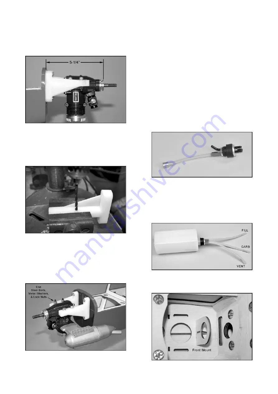
39) Set your engine in place on the beams of the engine
mounts. Slide the engine forward or aft on the engine mounts until
the front of the engine's thrust washer is 5-1/4" from the front of
the firewall. Double check to make sure that the engine is pointing
exactly straight forward, and then mark the locations of the engine
mounting holes onto the beams of the engine mounts, using a
center punch or sharpened nail.
❑
40) Now set your engine aside and unbolt the engine mounts
from the firewall. Drill clearance holes for your engine mounting
bolts all the way thru the engine mount beams at the four locations
you marked in the previous step. TIP: Secure the engine mounts
in a vise while you drill the holes. If at all possible use a drill press
instead of a hand drill - the job will be much easier and the holes
will be straighter.
IMPORTANT: DO NOT USE ANY TYPE OF SCREW TO MOUNT
YOUR ENGINE TO THESE MOUNTS. ALSO, DO NOT DRILL
AND TAP THESE ENGINE MOUNTS FOR BOLTS!
Doing so
may weaken them and cause failure. Mount your engine to these
mounts with steel bolts with flat metal washers and nylon insert
lock nuts. Drill clearance size holes for the bolts completely
through the mount beams. The mounting bolts should go through
the holes without binding.
NOTE: Bolts are not provided for mounting your engine because
not all engines suitable for the T-CLIPS use the same diameter
bolts. Many will use 6-32 size bolts, while some may use a larger
diameter bolt. It is up to you to acquire the correct size Bolts(4),
Flat Metal Washers)4), and Lock Nuts(4) to fit your engine. For
6-32 mounting bolts the correct clearance hole would be a 5/32"
dia. drill bit.
❑
41) Next assemble the Fuel Tank.
a) Locate the Rubber Stopper Assembly. There are three nylon
tubes going through the rubber stopper. Orient the stopper so
that one of the tubes is towards the top and then bend that tube
up at a 45-degree angle. Do not apply heat to the tube - it will
bend without heat. Just overbend it to nearly 90-degrees and then
let it relax, to see where it will end up. Repeat if necessary until
the tube will stay at 45-degrees.
b) Attach the metal Fuel Pick-Up Weight on one end of the sil-
icone Fuel Line Tubing that goes inside the tank. Cut the other
end of the fuel line tubing to a length that will allow the clunk to
reach the back of the tank, without getting stuck on the walls of
the tank. Test fit in the tank and adjust as necessary. With the
stopper assembly in place, the fuel clunk should sit just in front of
the rear of the tank and move freely inside the tank. If not pull the
assembly back out and trim the tubing back until the stopper
moves freely. The top of the vent tube should rest just below the
top of the tank. It should not touch the top of the tank.
c) Once you are satisfied with the fit of both the fuel clunk line
and the vent line you can tighten the machine screw to expand
the rubber stopper and seal the stopper in the tank. Do not over
tighten the screw as it can cause the tank to split. Attach three 6-
inch lengths of silicone fuel tubing (not furnished) to the tank and
label them appropriately as FILL, CARB, and VENT so you can
identify them after the tank is installed in the airplane.
❑
42) Install the fuel tank in the fuselage.
a) First glue the plywood fuel tank front mount in the notches
in the fuselage floor.
b) Slip the fuel tank in place, poking the neck of the tank into
the plywood front support.
13


