


5
hole locations onto the mounting blocks.
Remove the servo and drill pilot holes for the servo mounting
screws into the wood mounting blocks, using a #60 (1 mm) bit.
Use the mounting screws that came with your servo to secure the
servo to the mounting blocks.
Repeat this same procedure with the remaining aileron servo and
servo hatch.
❑
9) In this step, the servo arms will be centered onto the servo
output shaft. First, remove the servo output arm retaining screws
and remove the servo output arms.
Connect the two aileron
servos leads into a standard "Y" harness. Plug the "Y" harness
into the receiver. Turn your transmitter on and center the aileron
trim to neutral. Connect the receiver to a 4.8v battery pack. With
the system now on and working, reattach the two servo output
arms onto the two aileron servos, with the arms at 90
O
(or as close
to 90
O
as possible) and reinstall the output arm retaining screws
into each servo. If your radio system has "sub trim" capability, use
this feature to further center the output arms at 90
O
to the servo
body and centered within the servo hatch slot. Once the output
arms are both centered, cut off the opposite, unused end of each
arm. This ensures that the arm will not contact the covering on the
inside top of the wing when the servo tray is installed. Turn the
radio system off and unplug the servo leads from the "Y" harness.
❑
10) Connect a 6" servo lead extension onto each aileron servo
lead.
We always suggest securing these extensions at the
connectors, using a length of heat shrink tubing. This ensures that
the connection remains secure.
❑
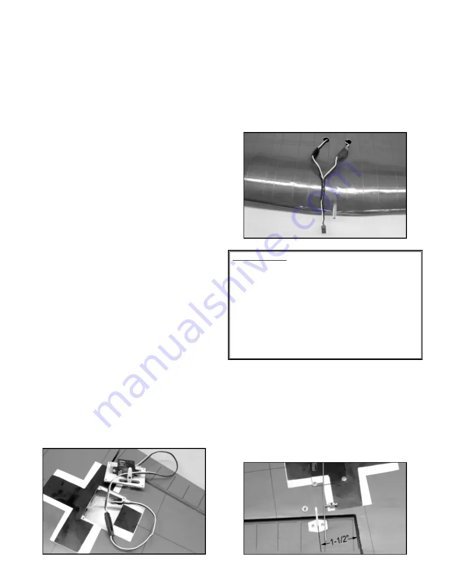
11) On the top surface of the wing, near the center joint, you will
be able to feel the location of two 1/2" diameter holes through the
covering. These are the exit holes for the aileron servo leads. Use
a sharp #11 blade to remove the covering from these holes. You
should then be able to see a small stick tack-glued to the inside top
sheeting with a string attached to it. This is the pull string, used to
pull the aileron servo leads through the wing ribs.
❑
12) Inside the aileron servo bay in each wing panel, the other
end of this string is attached to a small tack-glued stick. Break this
stick loose and unwind the string from the stick. This end of the
string is secured firmly to the connector end of the servo extension
lead (we like to tie this string tightly to the connector). With the
string in place to the connector, feed the connector and string into
the servo bay while gently pulling on the string at the exit hole in
the center of the wing. Start the connector down through the holes
in the wing ribs. Lightly pull back and forth until the connector
moves through one rib and up to another. Keep doing this until the
connector appears at the exit hole. Pull the connector up through
the hole and temporarily tape it to the wing surface. Now, mount
the servo hatch and servo in place to the bottom of each wing
panel, using the provided screws, removed earlier. Repeat this
procedure with the opposite servo hatch and wing panel.
❑
13) With both servo leads now through their respective exit
holes on the top center of the wing, remove the strings and plug
each lead into a standard "Y" harness.
Again, we suggest
securing these connections with short lengths of heat shrink
tubing.
❑
14) The aileron control horns are now installed onto the bottom
surfaces of each aileron. The vertical center arm of the control
horn is located 1-1/2" from the inboard from the end of the aileron,
with its four hole locations lined up with the hinge line. Hold the
control horn in this position and use a sharp pencil to mark the two
control horn mounting hole locations onto the surface of the
aileron.
At the two marks just made, use a #46 (2 mm) dia. bit to drill two
clearance holes completely through the aileron, 90
O
perpendicular
MODELER’S TIP: It happens to all of us now and then; the
factory installed servo lead string disappears into the wing! No
problem. Simply pull the string completely out of the wing and
attach a small weight, such as a metal nut or even a small split
shot sinker, to one end of the string. Insert the weighted end of
the string into the servo opening and start it down the holes that
are just behind the spars. With the wing on end and the center
of the wing below the servo well, gently shake the wing while
feeding the in the weighted string, listening for the weight to
drop through to the next rib.
When the center section is
reached, turn the wing upside down and shake the weight out
of the hole and you're back in business!