


.
Sawn Birch Plywood
2 1/16"x3/4"x1-5/8" Wing
Hold Down Plates
1 1/4"x1-1/2"x3" Landing
Gear Mount
Hardwood
I 1/4" dia.x2" BIRCH;
Wing Hold Down Dowel
2 1/4"x1/4"x2"
BASSWOOD; Grooved
Torque Rod Blocks
2 1/4"x3/4"x1" BASSWOOD;
Wing Hold Down Blocks
4 3/16"x3/8"x30" SPRUCE; Main
Wing Spars
Formed Wire Parts
1 1/16" dia. Tailwheel
Wire
1 3/32" dia. Elevator
Joiner
1 4-40x5" Threaded Rod- L.H.
Aileron Torque Rod (with
1/8"o.d. x1-1/2" Brass Bearing)
1I 4-40x5" Threaded Rod- R.H.
Aileron Torque Rod (with
1/8"o.d. x1-1/2" Brass Bearing)
Formed Plastic
1 .03 Clear Plastic;
Canopy
Miscellaneous Parts
2 Glass Filled Engine
Mounts
1 .090 Aluminum Landing
Gear
1 1" x 24" Fiberglass Tape (for
wing center and tailwheel wire)
1 6-3/4"x20" Decal
1I 10"x27" Decal
1 38"x50" Full-Size Plan
1 16 page Photo-Illustrated
Instruction Booklet
1 "The Basics of Radio Control"
Booklet
Hardware
4 #2x1/2" Sheet Metal
Screws (for control
horns)
3 6-32x1/2" Mounting
Bolts (for landing gear)
4 6-32x3/4" Mounting Bolts (for
engine mounts)
2 8-32x1-3/8" Mounting Bolts (for
wheel axles)
7 6-32 Blind Nuts
(4/engine mounts,
3/1anding gears)
4 8-32 Hex Nuts (2 per
axle)
2 1/4-20x -1/2" Nylon Wing Bolts 2 4-40 Nylon Aileron Connectors
5 2-56 R/C Links
(2/ailerons, I/elevator,
l/rudder, I/throttle)
1 Small Nylon Control
Horn (for rudder)
1 Medium Nylon Control Horn
(for elevator
2 .190"o.d.x24" Nylon Outer
Tubing (pushrods for elevator
and rudder)
1 .130"o.d.x30" Nylon
Inner Tubing (for
throttle pushrod)
1 1/16"x15" Steel Cable
(for throttle pushrod)
1 Solder Link (for throttle push
rod)
1 2-56 Threaded Coupler (for
throttle pushrod)
4 2-56x10" Threaded
Rods (2/ailerons,
l/elevator, l/rudder)
15 Easy Hinges
Notes Before Beginning Construction
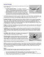
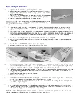
Any references to right or left refers to your right or left as if you were seated in the cockpit.
To build good flying models, you need a good straight building board. Crooked models don't fly well. The building board
can be a table, a workbench, a reject "door core" from the lumber yard, or whatever - as long as it is perfectly flat and
untwisted. Cover the top surface of the building board with a piece of celotex-type wall board or foam board, into which
pins can be easily pushed Don't hesitate to use plenty of pins during assembly to hold drying parts in their correct position.
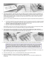
When pinning and gluing parts directly over the full-size plans, cover the plan with wax paper to prevent gluing the parts to
the plans. Don't use a ball point pen for making marks on the model during construction. If not sanded off, these ink marks
will show through the model's final finish. Use a pencil instead of a pen.
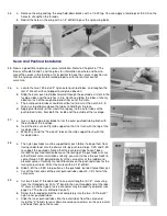
Leave all laser-cut parts in the sheets until needed in construction. Then remove the pieces from the sheets carefully. If
difficulty is encountered, do not force the part from the sheet - use a modeling knife to cut it free.
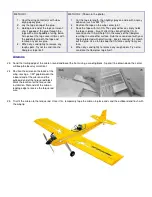
The laser-cut balsa and plywood parts can be identified using the plans and the "KEY TO LASER-CUT PARTS" below.
Mark the identification numbers on the corresponding parts before removing them from the laser-cut sheets. All of the
other parts can be identified by the "COMPLETE KIT PARTS LIST" above. Sort the different sizes of sticks and sheets into
individual piles to avoid confusion during building.
SPECIAL NOTE: Any future references to die-cut parts will actually be refering to laser-cut parts.
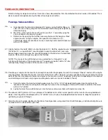
Summary of Contents for Four-Star 40 SIGRC44
Page 1: ......