


.
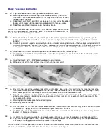
50. With the pushrods hooked up to the servos, you can now glue F-3S and F-4S to the front of F-3 and F-4, respectively, in
such a way to keep the bends at a minimum.
51.
This is a good time to install the nylon outer tubing for the throttle pushrod. Temporarily mount your engine to help locate
where the throttle pushrod will come through F-1. Follow the guidelines given in "The Basics of Radio Control" (page 8),
but stop before attaching the solder clevis (servo connector). Now is also a good time to plan your fuel tank installation and
routing of the fuel lines through F-1. Remove the throttle cable, engine, fuel tank, and the inner nylon push rods before
proceeding with covering.
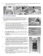
Tail Surfaces
52.
Sand the pre-cut 1/4" balsa stabilizer leading edges round except for the short length in the center, which should be left flat
to fit against the back of F-6.
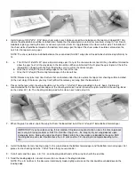
53.
a. Locate the two pre-cut 1/4" balsa elevators and sand their trailing edges round.
b. Draw a hinge line centered on the leading edge of each elevator. Use a sanding block to bevel the front of the
elevators using the hinge line as a guide.
c. Temporarily pin the elevators to the plans and mark where the 3/32" dia. music wire elevator joiner will attach.
Remove the elevators, then drill and groove their leading edges to accept the elevator joiner. Sand the joiner wire
and wipe it clean before gluing it to the elevators with Kwik-Set Epoxy. Be certain to keep the leading edges aligned
as the glue dries.
54.
Temporarily tape the elevators to the back of the stabilizer, then use a sanding block to sand both of them at the tips until
they match perfectly. The tips can be left square or sanded round if you prefer.
55.
a. Sand the pre-cut 3/16" balsa fin leading edge round.
b. Sand the trailing edge of the pre-cut 3/16" balsa rudder round.
c. Draw a hinge line centered on the leading edge of the rudder. Bevel the L.E. using the hinge line as a guide.
d. Sand a notch in the rudder leading edge to clear the elevator joiner wire as shown on the plans.
56.
a. Notch and drill the bottom of the rudder to accept the tailwheel wire.
b. Sand and wipe the tailwheel wire clean, then install it (without glue) on the rudder. Apply thin CA first (to penetrate)
and follow up with slow CA to completely fill around the wire .
c. Reinforce the tailwheel area with a 1-1/2" length of fiberglass tape wrapped around the bottom of the rudder. Use
thin CA to completely saturate the tape and surrounding wood. A second coat of thin CA will help fill the weave of
the fiberglass.
NOTE: Epoxy may be used in this step, but CA is faster and penetrates the entire tailwheel area, making it rock hard.
57.
The top of the fin or rudder may need sanding so that they line-up when installed. Temporarily pin or tape the stabilizer and
fin on the back of the fuselage, then tape the rudder to the fin so that its bottom edge is aligned with the fuselage bottom.
Remove the fin and rudder (which are still taped together) and sand the top edge until they match.
COVERING
General Instructions
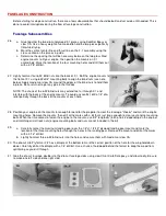
Before choosing the covering for your model, please refer to the list of approved covering materials that has been included
with this kit. The open-structure design of the Four-Star 40 wing relies partially on the covering to aid in torsional stiffness,
so it is very important that you use an approved covering material.
Summary of Contents for Four-Star 40 SIGRC44
Page 1: ......