


13
other end, connect the solder link to your engine's throttle arm.
Finally cut the cable to length inside the fuselage, leaving about
2" of extra length behind the brass pushrod connector. The extra
length will be useful when setting up the throttle travel limits
later on.
❑
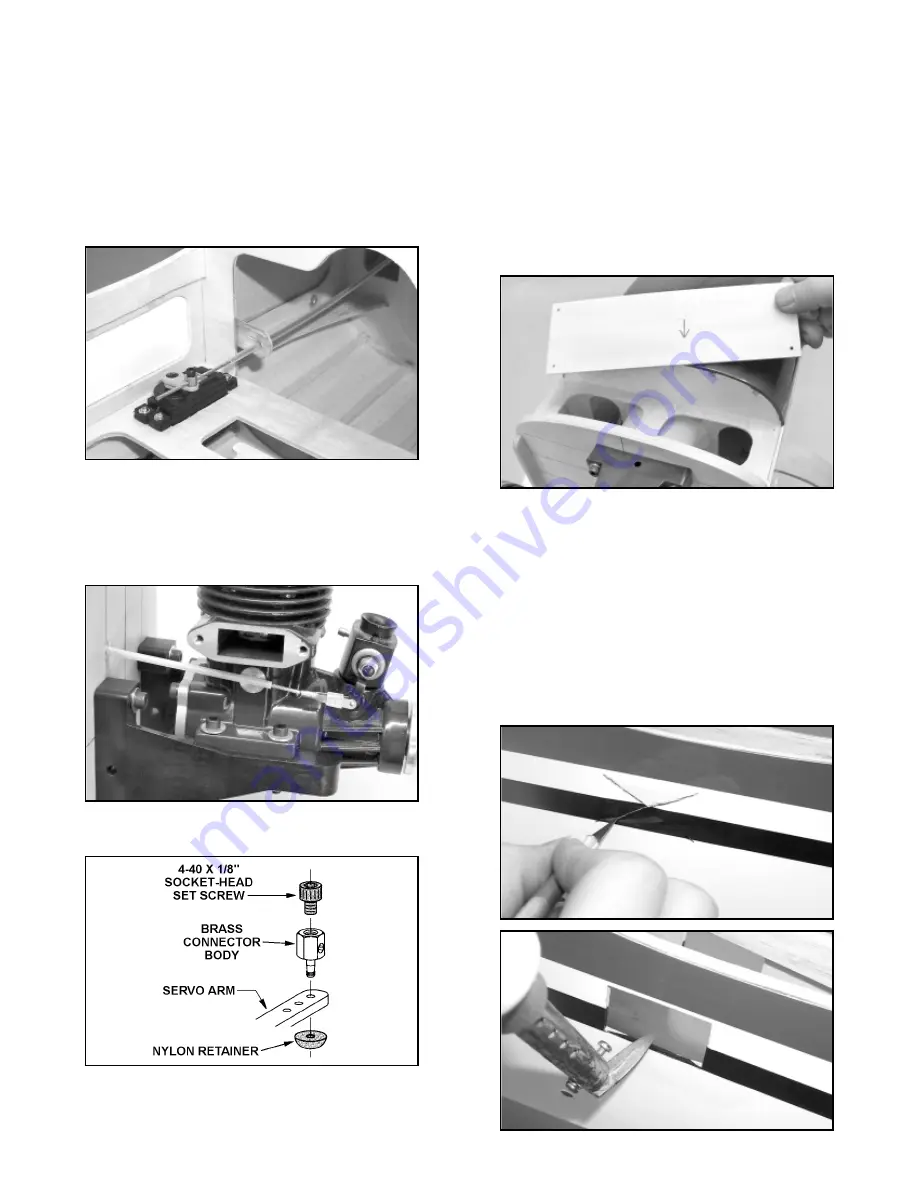
9) Fit the 1/8" x 2-9/16" x 7-7/8" plywood front fuselage hatch
onto the nose of the airplane. Hold the hatch in place while you
drill a 3/64" (or #56) dia. hole through each corner of the hatch and
on down through the fuselage plywood. Take the hatch off and
open up the holes in the hatch to 7/64"" dia., to allow clearance for
the screws. Screw the hatch in place with the M2.6 x 10mm PWA
screws provided.
ADDITIONAL FUEL PROOFING: It's a good idea to paint the
hatch, firewall and bare wood areas of the nose with a fuel-proof
paint such as clear dope, epoxy, enamel, or similar. A light coat of
fuel-proofer has been applied at the factory, but another coat will
increase the life of the model and treat the newly exposed wood
areas that you have drilled and/or cut out.
ATTACHING THE TAIL SURFACES
❑
1) Use a sharp #11 blade to open up the covering material
over the two elevator servo cutouts at the rear of the fuselage. Use
a trim seal iron to tack the loose covering around into these
cutouts. Trim and remove the excess covering material.
❑
4) Inside the fuselage, slip the plywood throttle tube support
over the end of the nylon pushrod tube and up against the forward
fuselage former. Position the plywood support so that it aims the
nylon tube directly at the throttle servo’s output arm. Then glue the
plywood support to the former in that location.
❑
5) Use a sharp razor blade to cut the nylon tube to length 1"
beyond the plywood tube support. Remove the tube and sand its
surface with 220 sandpaper to rough it a little. Reinstall the tube
and glue it in place to the firewall and the plywood tube support
with thick CA glue.
❑
6) Solder the 2-56 solder link to one end of the steel cable -
this is the carburetor end of the throttle pushrod. In addition to
attaching the solder link to the end of the cable, you should flow
some solder into the last 1" to 2" of cable (depending on your
specific installation) to stiffen it. Also flow solder into the last 1" of
the other end of the cable to stiffen it and keep it from unraveling.
❑
7) Install the brass pushrod connector assembly to the output
arm on the throttle servo, as shown in the drawing.
❑
8) From the firewall, insert the bare end of the steel cable
through the nylon tube. When you get it all the way in, insert the
end of the cable into the pushrod connector on the servo. At the