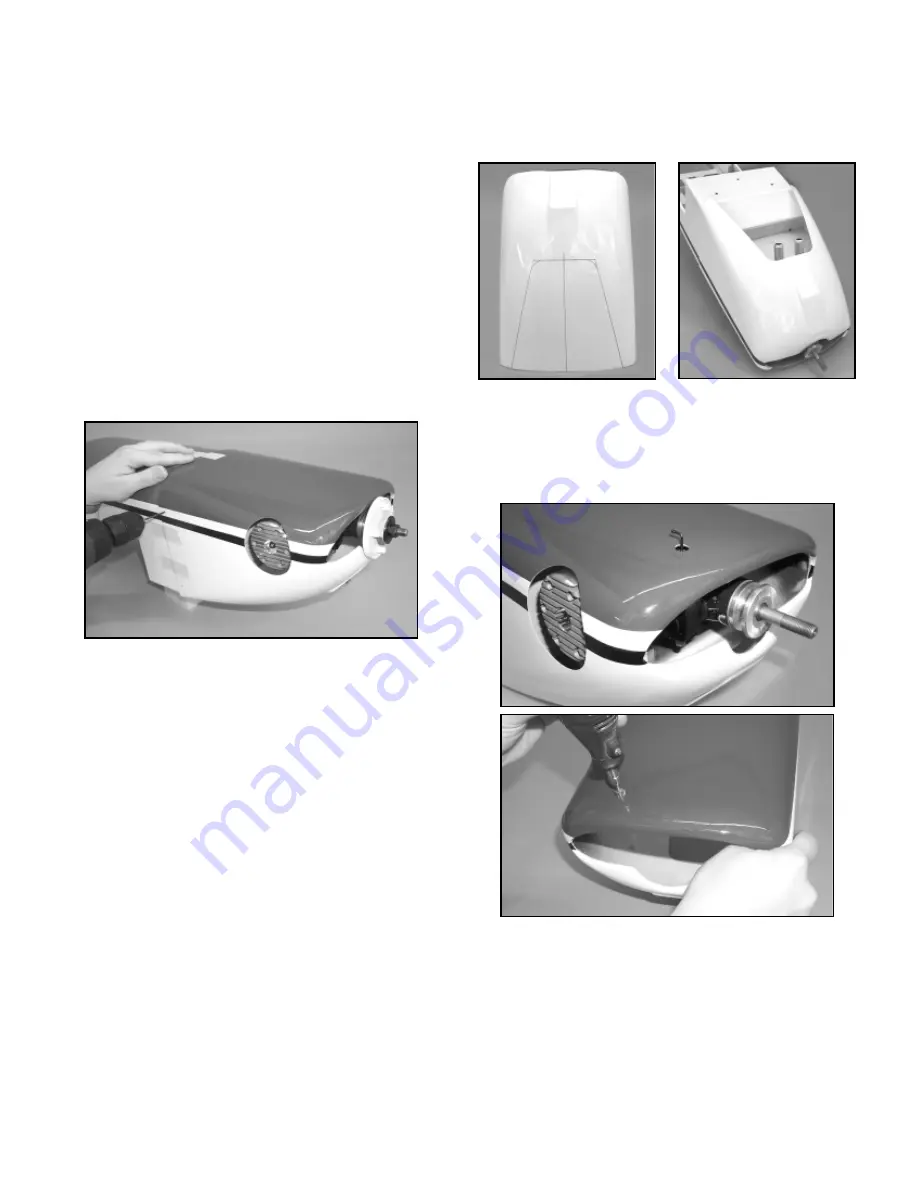
SIG Extra 300XS Assembly Manual Download Page 10

10

cut-off wheel for a sanding drum bit in your Dremel

®

Tool. Use the

drum sander bit to round the upper two corners and to lightly clean
up any jagged edges. Use 220 sandpaper to clean up the edges
of the cutout, without sanding the paint. Make sure the edges are
uniform and free of any loose glass. Remove all fiberglass dust
from the cowl with tack rag or with alcohol on a clean cloth.

5) Mount the trimmed cowl back onto the fuselage. In this step

you will determine the location for the hole required for access to
your engine's needle valve. This is easiest done using the penlight
mentioned earlier in step #1 and fine-tip marker pen. First find the
approximate location of where the needle valve will exit by looking
carefully at your engine carburetor. Mark that location on the cowl.

Now look a little closer and use the penlight to adjust the mark just
made from the outside of the cowl.

Reposition the mark as

required to get as close as possible to the exact needle valve 
location. Use the Dremel

®

Tool and a small tipped grinding bit to

make a small hole (maybe 1/16" in diameter) in the cowl, at the exit
mark just made. Chances are that you were quite close to the
actual exit point. Stick a piece of music wire into the hole, down to
the needle valve.

Carefully observe if the hole needs to be

repositioned to straighten up the wire, as if it were the needle valve.
Make another mark on the cowl and again use the Dremel

®

Tool to

open the hole just a little towards the correct position.

In this

manner, continue checking and adjusting the exit hole until it aligns 

2) Once the cowling is in place without any part of the engine

contacting it, push the cowl back onto the fuselage until the engine
prop mounting flange emerges from the front of the cowl. This
flange must clear the front of the cowl by at least 1/16" (1/16" to
1/8" is OK). Slip the spinner backplate in place over the engine
prop shaft, pushing it all the way back to the prop mounting flange.
Mount a prop or prop stub "dummy" in place on the drive shaft.
Tighten the prop assembly sufficiently to bring the spinner
backplate firmly in place against the prop mounting flange.
Recheck to make sure you have at least a 1/16" gap between the
back of the spinner backplate and the front of the cowl. Center the
spinner backplate to the cowl and use masking tape to secure the
back of the cowl to the fuselage, leaving the four pre-drilled
mounting holes along the back edge of the cowling uncovered.

3) With the cowl securely taped in place, use a 3/64" (or #56)

dia. drill bit to drill pilot holes in the fuselage, centered in each of
the four pre-drilled mounting holes in the cowl. Mount the cowl to
the fuselage with four M2.6 x 10mm PWA Screws provided.
Double check your work one more time to make sure that the cowl
is bolted on in the correct location and alignment. Then remove the
cowling from the fuselage.

4) An opening must now be made in the bottom of the cowling 

to allow engine cooling air to properly flow through and exit the
cowling. This is absolutely necessary for proper cooling!  Without
this opening, your engine will overheat and quit. If you are using a
2-stroke engine, such as the Irvine 1.20 or 1.50, or a 4-stroke such
as the Saito 1.20, 1.50, or the 1.80, we suggest using an opening
which measures 6-1/2" long from front to back, 6-1/2" wide at the
back edge by 3-1/2" wide at the front. This size opening allows the
exhaust pipes on the recommended SIG muffler for the Irvine
engines to clear the cowl with plenty of additional air exit area, as
well as allowing plenty of air for 4-stroke engines. The dimensions
of this opening may certainly be “customized" for your particular
engine/muffler set-up, as long as there is sufficient air exit area.

Stand the cowl upright on its rear edge, nose up, with the bottom
side facing you. Use a fine-point marker pen to draw an outline of
the area you need to cut out. Measure carefully to make sure that
the opening is properly centered and located. We suggest using a
circle guide to round the two upper corners of the cut out area for
a better look.

The air outlet can be easily cut from the fiberglass cowl using 
a Dremel

®

Tool and a large cut-off wheel.

Before cutting out 

the cowl opening be sure to wear safety glasses and a mask of
some kind to avoid inhaling any fiberglass dust.

Carefully cut 

the fiberglass, using the lines previously drawn. If you are careful,
you will find that you can get fairly close to the lines with the 
cut-off wheel. The goal is to remove most of the material within the
lines. Once the piece is cut and removed, exchange the cut-off

Summary of Contents for Extra 300XS

Page 1: ...h the pushrods coming off the top of each servo in direct line with the control horns This is done so the geometry of the servos pushrods and horns is exactly symmetrical on both sides providing the exact same response to control inputs for each elevator This is very important in an all out aerobatic machine like the EXTRA Normally in order to have this type of setup work properly with a standard ...

Page 2: ... Irvine 1 20 and 1 50 2 stroke engines extensively and found that both engines provide suitable power and are easy to install and operate in the EXTRA 300XS In the case of the Irvine 1 50 with a 16 x 8 APC prop we have excellent vertical performance not unlimited vertical but it will go straight up for an impressive distance much longer than most typical R C models When using a 2 stroke engine ins...

Page 3: ... 10 32 x 1 Socket Hd Mtg Bolts for engine mount 4 10 32 Blind Nuts for engine mount 4 10 Flat Metal Washers for engine mount 1 Decal Sheet PWA phillips washer style head NOTE ABOUT COVERING MATERIAL Your EXTRA 300XS ARF has been professionally covered with Oracover 10 White 54 Violet and 71 Black Note In the United States Oracover is sold under the name of Hangar 9 Ultracoat The equivalent Ultraco...

Page 4: ... Hardwood Wing Joiner right side up the greater angles are on the bottom 1 Locate the two pre covered aileron servo hatches and eight M2 6 x 10mm PWA Screws Trial fit the hatches into the aileron servo openings to determine which hatch goes in the right wing and which goes in the left wing Tape the hatches in place aligning their servo arm cutouts with the ones in the wing openings 2 Drill a 3 64 ...

Page 5: ...he wing panels use your radio system to center both servos and to check servo travel Make sure both servo output arms are 90O to the servos and that they are long enough to clear the wing s bottom surface during extremes of travel a Now attach 12 long servo extension chords to both aileron servos Note Be sure to put a piece of tape around the connecting plugs so they can t come apart while hidden ...

Page 6: ...easily Use a sharp 11 blade in your hobby knife to adjust ONE of the holes slightly to the left or right to achieve a good fit Once the wing dowels properly engage press the rear of the accept the square knuckle part of the hinge You need to countersink the holes to accept the knuckle part of the hinge so that the hinge can be pushed in far enough for the pivot point to line up with the front V po...

Page 7: ...are already pre drilled in the center to pass the nylon wing bolts Notice that there are also holes for the wing bolts pre drilled in the rear center section of each wing panel Hold one of the wing bolt plates in position on the BOTTOM of the wing aligning the hole in the plate with the bolt hole in the wing Use a pencil or fine tip marker to draw the outline of the plate onto the wing Do the same...

Page 8: ...ttach a solder link onto the unthreaded end of one of the threaded pushrods Thread a 4 40 hex nut onto the threaded end of the pushrod followed by a 4 40 threaded R C link Connect the solder link end of the pushrod to the aileron servo output arm Holding the other end of the pushrod up next to the aileron horn adjust the threaded R C link as needed to match its connecting pin to the horn Repeat th...

Page 9: ... are sunk securely into the back of the firewall Apply some epoxy glue around the flanges of the blind nuts to keep the nuts from coming loose Be careful not to get any glue in the threads of the blind nuts 7 With the engine mounts bolted on the firewall place your engine on the mounts Move the engine forward or backward on the mounts until you measure exactly 6 from the front face of the prop dri...

Page 10: ...gap between the back of the spinner backplate and the front of the cowl Center the spinner backplate to the cowl and use masking tape to secure the back of the cowl to the fuselage leaving the four pre drilled mounting holes along the back edge of the cowling uncovered 3 With the cowl securely taped in place use a 3 64 or 56 dia drill bit to drill pilot holes in the fuselage centered in each of th...

Page 11: ...is to make a simple 90O aluminum bracket to hold the valve mount it to the firewall and then make a small hole in the cowl to accept the fuel probe We mounted our filler bracket near the left edge of the firewall Our bracket was made from K S 1 16 thick aluminum sheet Drill one end of the bracket with a 3 8 dia hole to accept the fuel valve body and drill two 7 64 dia holes at the other end allowi...

Page 12: ...hat best suits the throttle arm on your engine Mount your throttle servo in the plywood tray using the grommets and mounting screws supplied with your radio system 2 Locate the 1 8 od x 18 Nylon Pushrod Tubing the 1 16 x 18 Stranded Steel Cable the 1 8 x 5 8 x 1 1 4 plywood Throttle Tube Support has one rounded end with a hole for the tube the Pushrod Connector assembly hex brass body nylon retain...

Page 13: ... seal iron to tack the loose covering around into these cutouts Trim and remove the excess covering material 4 Inside the fuselage slip the plywood throttle tube support over the end of the nylon pushrod tube and up against the forward fuselage former Position the plywood support so that it aims the nylon tube directly at the throttle servo s output arm Then glue the plywood support to the former ...

Page 14: ...in is absolutely 90O upright on the fuselage and that it is aligned straight with the centerline of the fuselage not turned left or right b When satisfied with the alignment use a felt tip pen to mark the fin location on top of the stab Take the fin off and carefully remove the covering material from the stab just inside of the lines NOTE Accurate alignment is ultra critical to the performance of ...

Page 15: ...Apply a coat of glue to the inside of the fairing where it will contact these areas Install the fairing pressing it firmly in place to make sure it contacts all gluing areas Clean up any excess glue with alcohol and use tape to secure the fairing in place Allow to dry 10 Mount the rudder servo in the center servo cutout in the fuselage using the grommets and screws supplied with your radio system ...

Page 16: ...e back and run it back through the copper tube Pull the tube up to the rigging coupler about 1 2 away from it Use pliers or a crimping tool to squeeze the copper tube tightly over the cable locking it in place Cut off the excess short end of the cable Thread an R C link onto the rigging coupler centering it on the threads Repeat this process to make the same type of end on the other piece of cable...

Page 17: ...s of silicone adhesive to lightly fasten the extension chords or the MIRACLE Y control pot in place to the model structure to keep them from flopping around during flight and possibly coming unplugged Finally plug the chord into your radio system to check the action of the elevator servos Make any corrections that may be required 19 Hinge the elevators to the stabilizer at this time Be careful to ...

Page 18: ...ors and use spray cement to glue it in place on the cockpit deck Last we mounted a 1 4 scale civilian pilot figure to the cockpit deck to finish off the cockpit detailing There are many brands of pilot figures available No matter which brand you use be sure to reinforce the bottom of the cockpit deck by epoxying a piece of scrap 1 32 or thicker scrap plywood underneath the area where the pilot wil...

Page 19: ... reproductions of some of the insignias that are typically seen on full scale aerobatic airplanes They are not intended to be a complete set of markings to duplicate one particular EXTRA 300XS However we think you ll agree that when applied to the SIG EXTRA as shown on the box label they look very realistic and believable Feel free to use all or only some of the decals in different locations as yo...

Page 20: ...at a good straight edge a ruler and a hobby knife with sharp 11 blades We also suggest that you have some trim tape handy for making temporary guidelines 1 8 width or so is perfect for help in aligning the decals First spray the surface of the model where the decal is to be placed with a soapy water mixture Then peel the backing sheet completely off the decal being careful not to let the sticky si...

Page 21: ...oved aft an airplane will become more responsive in all axis but it will be especially noticeable to a model pilot in pitch up and down We have flown the EXTRA at the 30 location and found it to be manageable with excellent aerobatic capabilities However we did notice an increase in pitch sensitivity and had decrease the elevator throw to compensate Softening elevator response with a reasonable ex...

Page 22: ...safely for years Your R C model airplanes should receive the same consideration While still at the flying field and after you ve finished flying for the day empty the fuel tank completely with your fuel pump After draining the tank start the engine and let it run the fuel lines totally dry Old glow fuel that has been left in the tank for more than a few hours will not run properly After each flyin...

Page 23: ...23 EXTRA 300 LOG BOOK Date of first flight Comments ...

Page 24: ...The color and markings of this ARF kit do not duplicate one particular full scale Extra 300XS Rather they are a realistic selection of markings typically seen on many full scale aerobatic airplanes 24 ...

Page 25: ...ther model size or full size are not toys Because of the speeds that airplanes must achieve in order to fly they are capable of causing serious bodily harm and property damage if they crash IT IS YOUR RESPONSIBILITY AND YOURS ALONE to assemble this model airplane correctly according to the plans and instructions to ground test the finished model before each flight to make sure it is completely air...

Page 26: ...ng the most power at a reasonable cost First Place Engines are your best choice for large gasoline powered model airplane power plants All engines use piston and cylinder assemblies from world renowned manufacturers such as Husqvarna and Sachs Makita insuring long life and easy operation Using state of the art CNC machines First Place produces all other major components from high quality billet al...

Reviews: