19
PANEL FUNCTIONS & DESCRIPTIONS
1
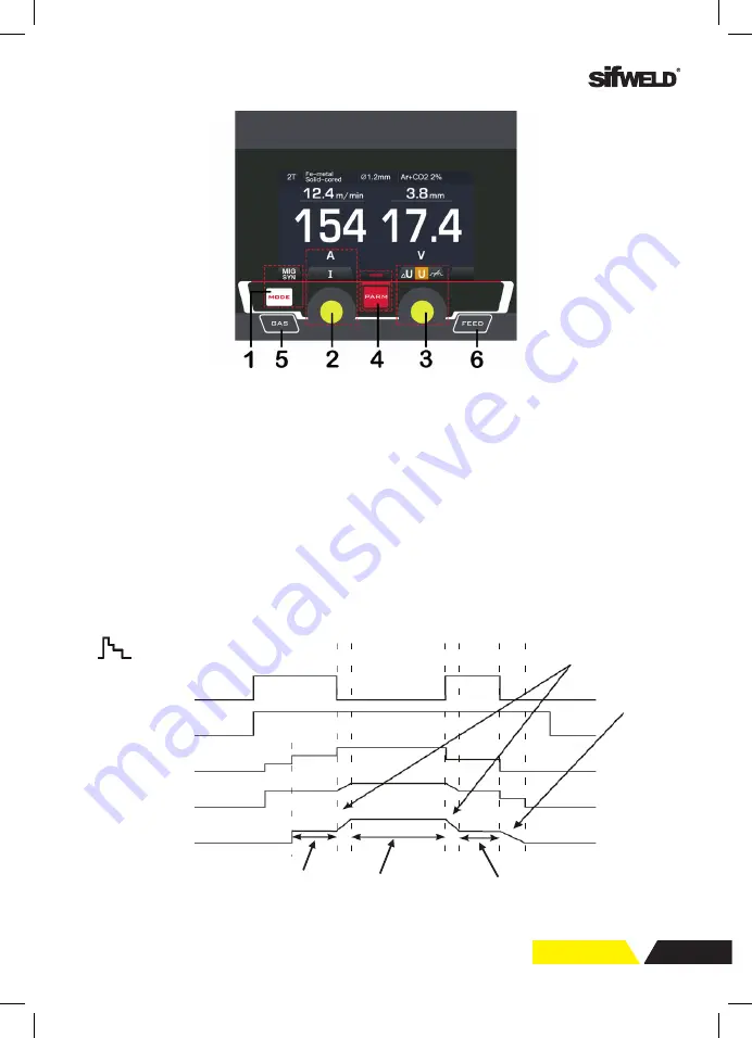
§3.2.5 MIG SYN display introduction
The operator simply sets the welding current like MIG welding and the machine
calculates the optimal voltage and wire speed for the material type, wire type and size
and shielding gas being used. Obviously other variables such as welding joint type and
thickness, air temperature affect the optimal voltage and wire feed setting, so the
program provides a voltage fine tuning function for the synergic program selected. Once
the voltage is adjusted in a synergic program, it will stay fixed at this variation when the
current setting is changed. To reset the voltage for a synergic program back to factory
default, change to another program and back again.
1. Welding mode button
: Press it to select MIG SYN welding mode.
2. L parameter knob
: Rotate it to adjust wire feeding speed. In functional parameter
interface, rotate it to select parameters.
3. R parameter knob
: Rotate it to adjust parameters.
4. Functional button
.
5. Manual shield gas check button.
6. Manual wire feed button.
FUNCTION INTERFACE
1. Trigger mode:
2T/ 4T/ S4T/ Spot weld. (No Spot weld in MIG Dual Pulse.)
2. Wire material:
SS solid-cored/ Fe solid-cored/ Fe flux-cored/ Al-Mg solid-cored/ CuSi.
3. Wire diameter:
0.6~1.6mm.
4. Shield gas:
CO2 and Ar+CO2 20%.
5. Pre flow time:
0~10s.
PANEL FUNCTIONS & DESCRIPTIONS
1
Function interface:
1. Trigger mode
: 2T/ 4T/ S4T/ Spot weld. (No Spot weld in MIG Dual Pulse.)
2. Wire material
: SS solid-cored/ Fe solid-cored/ Fe flux-cored/ Al-Mg solid-cored/
CuSi.
3. Wire diameter
: 0.6~1.6mm.
4. Shield gas
: CO
2
and Ar+CO
2
20%.
5. Pre flow time
: 0~10s.
S4T trigger mode:
Gun Switch
Gas Supply
Wire Feed
Output Voltage
Output Current
Welding condition
Initial condition
End Current condition
Transition Time
Burnback Time
S4T mode


