


AirLink RV50 Series Hardware User Guide
40
4117313
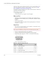
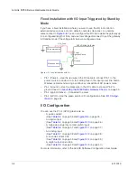
Figure 3-15: Digital Output / Open Drain
Step 5 — Check the gateway operation
1.
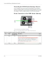
When power is supplied to the AirLink RV50
Series gateway
, it powers up
automatically, as indicated by the flashing LEDs. If it does not turn on, ensure
that the:
·
Power connector is plugged in and supplying voltage between 7 – 36 V.
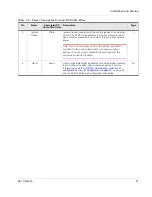
Note: Although the RV50
Series gateway
operates in the range 7 – 36 V, low
voltage standby mode is enabled by default (as of ALEOS 4.5.2), so in
order to avoid the gateway powering into standby mode, ensure that it is
supplied with more than 9 V at startup. (If desired, you can change the low
voltage standby settings once the gateway is operational.) If the Power LED
is red, the gateway is in standby mode.
·
Ignition Sense (pin 3) is connected to the battery or power source (see
on page 29 for details)
RV50
Series gateway
Pin 4
Protection
circuitry
V
in
External pull-up
On/Off
Off
Internal Pull-up
Resistor
Vcc
Table 3-9: Digital Output / Open Drain
Pull-up
State
Minimum
Typical
Maximum
Units
Comments
Off
Off
Open Circuit
—
—
—
—
Active
Low
—
—
0.5
V
5 mA,
≤
5 V
Summary of Contents for AirLink RV50 Series
Page 1: ...AirLink RV50 Series Hardware User Guide 4117313 Rev 3 ...
Page 2: ......
Page 6: ...AirLink RV50 Series Hardware User Guide 6 4117313 ...
Page 10: ...AirLink RV50 Series Hardware User Guide 10 4117313 ...
Page 18: ...AirLink RV50 Series Hardware User Guide 18 4117313 ...
Page 50: ...AirLink RV50 Series Hardware User Guide 50 4117313 ...
Page 62: ...AirLink RV50 Series Hardware User Guide 62 4112895 ...
Page 66: ...AirLink RV50 Series Hardware User Guide 66 4117313 ...
Page 77: ......
Page 78: ......