background image

 Instruction Manual

Page:  8

Model 3100 Series Flame Detector (11/04)

3.3.5 Auxiliary Relay

The Auxiliary Relay connector is located be-
tween the Power and Fire Relay connectors.
The connection points are labeled “Aux In”
and “Aux Out”.  The Aux. Relay is config-
ured for Normally Open (3100-03 and 3100-
04), or Normally Closed (3100-02 and 3100-
05) operation at the factory.

3.3.6 4-20 mA Connections

The 4-20 mA connections are connected at
the J2 connections The positive side of the
4-20 mA circuit is connected to Pin 7 and
negative side to Pin 6.

3.4 Testing

The Model 3100 Flame Detector uses ongoing self-
test functions which will indicate a fault if any of
the functions fail to pass.  If an end to end test is
required, a 1 sq. ft. pan with 1 inch of water and 1/
8 inch of kerosene set at the max. distance set by
the sensitivity settings may also be used. The detec-
tor should alarm within 5 seconds of ignition of the
fire.

The Model 3140 Flame Tester is also available. It
simulates a UV/IR flame signature by emitting a
steady state UV signal and modulated IR signal at a
flicker frequency of 5 to 10 Hs.

NOTE:

Because of the danger involved with
fire testing all safety precautions
must be observed.

4.0 MAINTENANCE

The self-test functions eliminate the need for most
regular maintenance procedures.  If a detector indi-
cates a fault, use the troubleshooting section of this
document to correct the fault.  Contact the local
“authority having jurisdiction” or consult the local
codes for any maintenance they may require for the
type of system installed.

4.1 Lens Cleaning

The most common fault is a Lens Test Fault.  Regu-
lar cleaning of the Lens will eliminate this type of
fault.  The frequency will depend on the cleanliness
of the area where the detector is installed and how
the detector is mounted.  A detector which is pointed
down should require less cleaning than one that is
pointed up.  An area which has lots of oil particu-
lates or dust will require more frequent cleaning than
one that is oil and dust free.  The frequency of the
Lens Test Fault will indicate how often cleaning is
necessary.  If the device is failing the “Lens test” to
often it may be necessary to install a dust shroud,
realign the detector, or change the detectors mount-
ing location.

To clean the lens:  Wipe the lens surface and grill
with a clean lint free cloth.  If more extensive clean-
ing is required use denatured or Isopropyl alcohol
and a clean lint free cloth.  

Do not use any silica

based solvents. (Most common glass cleaners are
silica based and should not be used to clean the
lens.)

Summary of Contents for 3100-01

Page 1: ...MODEL 3100 XX FLAME DETECTOR ...

Page 2: ...owing Sierra Monitor products Model Description 3100 01 Flame Detector Standard 3100 02 Flame Detector Enhanced Relay 3100 03 Flame Detector Enhanced Relay 3100 04 Flame Detector Enhanced Relay 3100 05 Flame Detector Enhanced Relay 3100 06 Flame Detector Flame Detector 4 20mA The instructions are effective for the above models as of March 1 1997 Instruction Manual Part Number T15007 Rev C2 Applica...

Page 3: ...ral Precautions 7 3 2 Housing and Conduit 7 3 3 Connection 7 3 4 Testing 8 4 MAINTENANCE 8 4 1 Lens Cleaning 8 5 TROUBLESHOOTING 9 6 SPECIFICATIONS 11 7 WARRANTY 11 APPENDICES A FIGURES A 1 Exploded View 12 A 2 Housing Dimensions 12 A 3 Common Wiring Configurations 13 A 4 Enhanced Series Wiring Connections 14 B TABLES 15 B 1 Dip Switch Settings 15 B 2 Connectors 16 B 3 Verify Aux Relay Configurati...

Page 4: ...y which may be connected as normally open or normally closed contacts Models 3100 02 03 04 and 05 have in addition to the Fire and Faults relays a Fire Verify system and an Auxiliary Fault system The Fire Verify system adds a field ad justable level of certainty to the declaration of a verified fire The Auxiliary Fault system will acti vate the Aux Relay for the Lens Test fault This allows a separ...

Page 5: ...tinuously monitoring the internal systems When a fault is detected the Fault Relay is de energized In Fault Mode the LEDs will flash a code indicating the type of fault Afault indication may mean the device is unable to detect a fire or that a device has become unreliable i e a Voltage Low fault For most faults the detector will return to Normal Mode when the fault condi tion is corrected The Mode...

Page 6: ...e same frequency or frequencies used by the detector to sense a fire may impact the detector s ability to see the fire Care should be taken to minimize radiant energy sources within the detectors Field of View Because of the variety of environments and conditions a factory trained technician or quali fied P E should be consulted before deciding on the location of devices The Model 3100 Detector us...

Page 7: ...t de energize when a flame is not present for a short period of time For the detector to be set to Non latching both Fire Output and Verify Output must be set to Non latching If either the fire out put or the verify output is set to Latching then the detector will be set to Latching When the detector is set to Latching the LED s will indicate an alarm until the device is reset regardless of the fi...

Page 8: ...t indication The de tector is disabled if a fault 2 or 3 is indicated 2 7 Relay operation See Figure 2 4 The Model 3100 01 has two relays the enhanced Models 3100 02 03 04 and 05 have four relays The function of the Fire and Fault Relays is the same on all models The Verify Relay and Aux Relay is only available on the enhanced models All relay connections are made at the connectors lo cated on the...

Page 9: ...fy In and Verify Out provides connections for nor mallyopencontactsonthe3100 02and3100 04 or normally closed contacts on the 3100 03 and 3100 05 The configuration of Nor mally Open or Normally Closed contacts is fixed and can only be changed by the fac tory 2 7 4 Auxiliary Fault The Aux Relay is energized whenever the detector fails the Lens Check test This fault indicates the detectors inability ...

Page 10: ... to various systems All connections are made on the back of the Model 3100 Flame Detector Module Remove the housing cover from the housing base Loosen the two slot ted head captive screws located on the top of the PC board Lift the Detector Module out of the housing base Strip and connect the wires to the connectors located on the back of the Detector Module 3 3 1 Power Power for the 3100 01 02 03...

Page 11: ... must be observed 4 0 MAINTENANCE The self test functions eliminate the need for most regular maintenance procedures If a detector indi cates a fault use the troubleshooting section of this document to correct the fault Contact the local authority having jurisdiction or consult the local codes for any maintenance they may require for the type of system installed 4 1 Lens Cleaning The most common f...

Page 12: ...libration Fault Calibration constants have been corrupted Factory service is required 5 2 4 Fault Type 4 Voltage Low Fault The input voltage is below 15 VDC Re move the Detector Module from the hous ing With the detector connected to power measure the voltage between Pin 1 and Pin 4 on the Power connector J5 The volt age should be between 15 32 VDC If the voltage is out of range check external wir...

Page 13: ...me on the detector is operating normally Check external alarm initiating cir cuit wiring 2 If the relay closes and the LEDs remain off or the relay remains open and the LEDs come on the detector needs factory service 3 If the relay remains open and the LEDs re main off contact the factory for further diag nostic information ...

Page 14: ...d hereunder including all implied warranties of merchant abilityandfitnessandtheexpresswarrantiesstatedherein are in lieu of all obligations or liabilities on the part of SMC for damages including but not limited to conse quential damages arising out of or in connection with the use or performance of the product Sensitivity 1 ft sq Pan fire on axis 80 feet within 5 seconds using standard fuel Swit...

Page 15: ...Instruction Manual Page 12 Model 3100 Series Flame Detector 11 04 Figure A 2 Model 3100 Series Dimensions Figure A 1 Model 3100 Series Exploded View APPENDIXA ...

Page 16: ...Model 3100 Series Flame Detector 11 04 Page 13 Instruction Manual Figure A 3 Model 3100 Series Common Wiring Connections ...

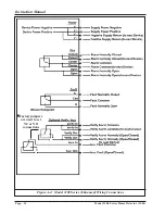
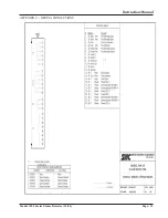
Page 17: ...Instruction Manual Page 14 Model 3100 Series Flame Detector 11 04 Figure A 4 Model 3100 Series Enhanced Wiring Connections Factory jumpers are used to set NC or NO connections ...

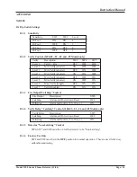
Page 18: ...F OFF ON Level 5 Min Verify shorter ON OFF ON Level 6 Max Verify longer OFF ON ON Level 7 Verify Disabled ON ON ON B 1 3 Fire Output Latching Control Fire Output Description SW6 Latching Alarm until Power down Reset OFF Following Alarm until no fire 5 to 10 sec ON B 1 4 Verify Relay Latching Control 3100 02 03 04 and 05 Models only VerifyRelay Description SW7 Latching Alarm until Power down Reset ...

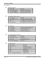
Page 19: ...f Relay Pin 6 Right Most Aux Fault Relay NO or NC Side of Relay B 2 3 Fault Connector J4 Fault Relay Description Normally Energized State Pin 1 Left Most Normally Closed Side of Relay Pin 2 Middle Common Side of Relay Pin 3 Right Most Normally Open Side of Relay B 2 4 Power Communications Connector J5 Power Comm Description Pin 1 Left Most Pin 5 Power DC Pin 2 Pin 6 Communication RS 485 Pin 3 Pin ...

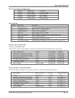
Page 20: ...s the detectors ability to tolerate both modulated and unmodulated false alarm stimuli FalseAlarms Source Distance Unmodulated Modulated Resistive Electric Heater 1320 Watt 6 Feet No Response No Response Fluorescent Lights 2 40 Watt Bulbs 6 Feet No Response No Response Halogen Light 500 Watt 10 Feet No Response No Response Incandescent Light 100 Watt 6 Feet No Response No Response Arc Welder 50 Wa...

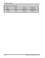
Page 21: ...11 04 B 7 Detector Response to Fuels Table Fuel Distance Fire Size Response Time Heptane 80 Feet 1 Square Foot Less than 3 sec Silane 50 Feet 18 inch jet Less than 3 sec Hydrogen 15 Feet 18 inch jet Less than 5 sec Kerosene 75 Feet 1 Square Foot Less than 5 sec ...

Page 22: ...Model 3100 Series Flame Detector 11 04 Page 19 Instruction Manual APPENDIX C WIRING CONNECTIONS ...

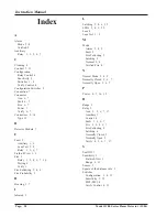
Page 23: ...1 2 4 6 7 16 Testing 8 Verify 1 Fire Following 2 4 6 Fire Probability 2 H Housing 1 7 I Infrared 3 L Latching 2 4 6 15 LEDs 2 4 5 20 Lens 8 Lens Test 1 2 M Mode Alarm 2 4 5 Fault 5 Fire Following 2 Latching 2 Normal 2 4 Verified Fire 4 N Normal Mode 2 4 5 Normally Closed 2 6 7 Normally Open 2 6 7 P Power 4 7 16 19 R Range 3 Relay 5 Aux 2 5 6 7 17 Auxiliary 1 Control 4 Fault 1 2 6 7 Fire 1 2 4 6 7 ...

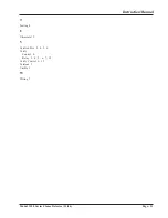
Page 24: ...del 3100 Series Flame Detector 11 04 Page 21 Instruction Manual T Testing 8 U Ultraviolet 3 V Verified Fire 2 4 5 6 Verify Control 4 Relay 2 4 5 6 7 15 Verify Control 6 15 Versions 2 Visible 3 W Wiring 7 ...

Reviews: