Description, device design, dimension drawing
2.4 Status displays and signaling
SITOP SEL1200-1400
Manual, 06.2019, A5E46496083-1-76
13
2.4
Status displays and signaling
6EP4438-7FB00-3DX0
6EP4438-7EB00-3DX0
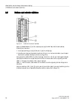
Group signal contact (13, 14)
④
floating relay contact (NO contact),
contact rating: 24 V AC/0.1 A; 30 V DC/0.1 A
NOTICE: It is not permissible that the signaling contact is connected to the line
voltage!
Remote reset (RST)
④
non-isolated 24 V DC input
Signal level "High" for > 15 V
Indicator light and pushbutton
(ON/OFF/RST) for each output
⑥
Three-color LED: rot, green and orange
Selector switch for diagnostic interface
(COM)
⑦
Switchover between signaling the status of the output channels and communica-
tion at the signaling contact.
Figure 2-4
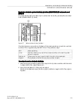
Status displays and signaling
The operating state of the outputs is displayed using multi-color LEDs at the front of the
device. Symbols indicate the significance of each LED, which are listed in the following table.
LED off
LED is continuously lit
LED flashes
Summary of Contents for SITOP SEL1200
Page 8: ...Safety instructions SITOP SEL1200 1400 8 Manual 06 2019 A5E46496083 1 76 ...
Page 26: ...Mounting removal SITOP SEL1200 1400 26 Manual 06 2019 A5E46496083 1 76 ...
Page 46: ...Safety approvals EMC 7 3 EMC SITOP SEL1200 1400 46 Manual 06 2019 A5E46496083 1 76 ...
Page 48: ...Ambient conditions SITOP SEL1200 1400 48 Manual 06 2019 A5E46496083 1 76 ...
Page 50: ...Environment SITOP SEL1200 1400 50 Manual 06 2019 A5E46496083 1 76 ...


