Measured Value Monitoring Functions
247
7UM62 Manual
C53000-G1176-C149-3
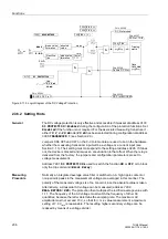
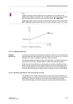
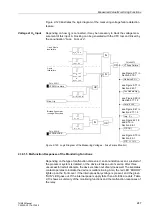
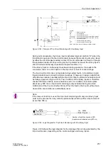
Figure 2-120 illustrates the logic diagram of the measuring voltage failure detection
feature.
Voltage at U
E
Input
Depending on how U
E
is connected, it may be necessary to block the voltage mea-
surement of this input. A blocking can be generated with the CFC tool and linked by
the annunciation “
Fuse Failure
“.
Figure 2-120 Logic Diagram of the Measuring Voltages – Fuse Failure Monitor)
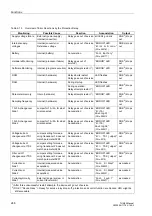
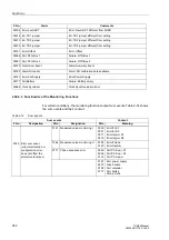
2.38.1.5 Malfunction Responses of the Monitoring Functions
Depending on the type of malfunction discovered, an annunciation is sent, a restart of
the processor system is initiated, or the device is taken out of service. After three
unsuccessful restart attempts, the device is taken out of service as well. The live status
contact operates to indicate the device is malfunctioning. Also, the red LED ”ERROR”
lights up on the front cover, if the internal auxiliary voltage is present, and the green
”RUN” LED goes out. If the internal power supply fails, then all LEDs are dark. Table
2-13 shows a summary of the monitoring functions and the malfunction responses of
the relay.
FNo. 05011
OR
&
U
2
/U
1
> 0,4
UL1 < 10 V
&
UL2 < 10 V
&
UL3 < 10 V
Gen. trip
FNo. 05010
&
&
FNo.06575
OR
OR
Undervolt. U <
Imp. Z <
O/C f(U)
O/C I > + U <
1- and 2-pole
fuse failure
3-pole
fuse failure
Blocked if generator
running without load
see Figure 2-71 in
Section 2.19.1
see Figure 2-61 in
Section 2.17.1.3
see Figures 2-18
and 2-19 in
Section 2.8.1
see Figure 2-10 in
Section 2.6.1
Imp. I>+U<
see Figure 2-59 in
Section 2.17.1.2
I
2
/I
1
< 0.2
|I
1
- I
N
| > 0.5 I
N
I
1
< 0.1
U
1
< 0.1
Inv. Underv.Up <


