Functions
52
7UM62 Manual
C53000-G1176-C149-3
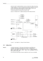
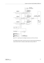
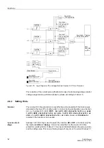
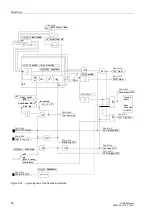
Figure 2-19
Logic Diagram of the Voltage-Restraint Inverse O/C Time Protection
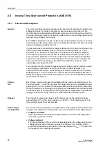
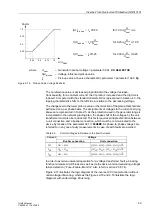
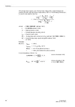
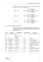
The reduction of the current pick-up threshold in case of a decreasing voltage (control
voltage assignment) is performed phase by phase according to Table 2-5.
2.8.2
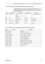
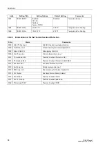
Setting Hints
General
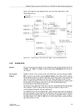
The inverse O/C time protection is only effective and accessible if this function was
allocated to the input CTs of either side 1 or side 2 during configuration (see Section
2.2), i.e. if address
=
with IEC-characteristic on side
1
,
with ANSI-characteristic on side 1
,
with IEC-characteristic on
side 2
or
with ANSI-characteristic on side 2
was set.
Disabled
is
selected if the function is not needed.
Ip overcurrent
stage
Address
is used to switch the function
ON
or
OFF
, or to block only the
trip command (
Block Relay)
. It must be noted that, for the inverse O/C time
protection, a safety factor of about 1.1 has been included between the pick-up value
and the setting value. This means that a pickup will only occur if a current of about 1.1
Tripping
matrix
&
&
&
FNo. 01900
FNo. 01897
FNo. 01896
FNo. 01898
IL1
IL2
IL3
FNo. 01883
FNo. 01892
FNr. 000361
Fuse Failure
Control
voltages in
relation
to
the
fault
current
UL1
UL2
UL3
Ux1
Ux2
Ux3
Ux=Un
FNo. 01899
OR
OR
OR
TMin
TRIP CMD

