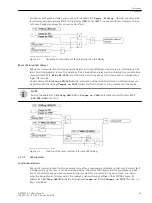


voltage of the switched feeder. This setting does not apply for a close command via the integrated control
functions. If the synchronism check is desired, the device must either feature the integrated synchronism
check function or an external device for synchronism check must be connected.
If the internal synchronism check is to be used, the synchronism check function must be enabled; an addi-
tional voltage U
sy2
for synchronism check has to be connected to the device and this must be correctly para-
meterised in the Power System Data 1 (address 210
U4 transformer
=
Usy2 transf.
and the associated
factors).
If no synchronism check is to be performed with manual closing, set
MAN. CLOSE
=
w/o Sync-check
. If a
check is desired, set
with Sync-check
. To not use the MANUAL CLOSE function of the device, set
MAN.
CLOSE
to
NO
. This may be reasonable if the close command is output to the circuit breaker without involving
the 7VK61, and the relay itself is not desired to issue a close command.
For commands via the integrated control (on site, DIGSI, serial interface) address 1152
Man.Clos. Imp.
determines whether a close command via the integrated control regarding the MANUAL CLOSE handling for
the protection functions (like instantaneous re-opening when switching onto a fault) is to act like a MANUAL
CLOSE command via binary input. This address also informs the device to which switchgear this applies. You
can select from the switching devices which are available to the integrated control. Select the circuit breaker
which operates for manual closure and, if required, for automatic reclosure (usually Q0). If
none
is set here, a
CLOSE command via the control will not generate a MANUAL CLOSE impulse for the protection function.
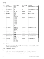
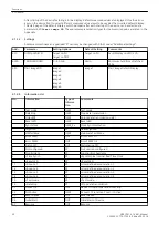
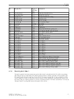
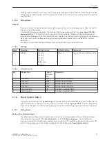
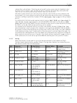
Settings
Addresses which have an appended “A” can only be changed with DIGSI, under “Additional Settings”.
The table indicates region-specific presettings. Column C (configuration) indicates the corresponding secon-
dary nominal current of the current transformer.
Addr.
Parameter
C
Setting Options
Default Setting
Comments
1103
FullScaleVolt.
1.0 .. 1200.0 kV
400.0 kV
Measurement: Full Scale
Voltage (100%)
1104
FullScaleCurr.
10 .. 5000 A
1000 A
Measurement: Full Scale
Current (100%)
1107
P,Q sign
not reversed
reversed
not reversed
P,Q operational measured
values sign
1130A
PoleOpenCurrent
1A
0.05 .. 1.00 A
0.10 A
Pole Open Current
Threshold
5A
0.25 .. 5.00 A
0.50 A
1131A
PoleOpenVoltage
2 .. 70 V
30 V
Pole Open Voltage
Threshold
1135
Reset Trip CMD
CurrentOpenPole
Current AND CB
Pickup Reset
CurrentOpenPole
RESET of Trip Command
1136
OpenPoleDetect.
OFF
Current AND CB
w/ measurement
w/ measurement
open pole detector
1150A
SI Time Man.Cl
0.01 .. 30.00 sec
0.30 sec
Seal-in Time after MANUAL
closures
1151
MAN. CLOSE
with Sync-check
w/o Sync-check
NO
NO
Manual CLOSE COMMAND
generation
1152
Man.Clos. Imp.
(Einstellmöglichkeiten
anwendungsabhängig)
none
MANUAL Closure Impulse
after CONTROL
2.1.5.2
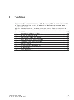
Functions
2.1 General
SIPROTEC 4, 7VK61, Manual
39
C53000-G1176-C159-5, Edition 05.2018
Summary of Contents for SIPROTEC 4 7VK61
Page 8: ...8 SIPROTEC 4 7VK61 Manual C53000 G1176 C159 5 Edition 05 2018 ...
Page 10: ...10 SIPROTEC 4 7VK61 Manual C53000 G1176 C159 5 Edition 05 2018 ...
Page 16: ...16 SIPROTEC 4 7VK61 Manual C53000 G1176 C159 5 Edition 05 2018 ...
Page 176: ...176 SIPROTEC 4 7VK61 Manual C53000 G1176 C159 5 Edition 05 2018 ...
Page 224: ...224 SIPROTEC 4 7VK61 Manual C53000 G1176 C159 5 Edition 05 2018 ...
Page 264: ...264 SIPROTEC 4 7VK61 Manual C53000 G1176 C159 5 Edition 05 2018 ...
Page 270: ...270 SIPROTEC 4 7VK61 Manual C53000 G1176 C159 5 Edition 05 2018 ...
Page 276: ...276 SIPROTEC 4 7VK61 Manual C53000 G1176 C159 5 Edition 05 2018 ...
Page 346: ...346 SIPROTEC 4 7VK61 Manual C53000 G1176 C159 5 Edition 05 2018 ...


