


current asymmetry is also detected (see margin heading “Current Symmetry”), the device issues the message
Fail Conductor
(No. 195).
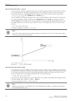
Voltage Symmetry
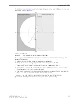
During normal system operation the voltages are assumed to be largely symmetrical. The symmetry is moni-
tored in the device by magnitude comparison. The smallest phase voltage is compared to the largest. Asym-
metry is recognized if:
|U
min
| / |U
max
| <
BAL. FACTOR U
as long as |U
max
| >
BALANCE U-LIMIT
Thereby U
max
is the largest of the three phase-to-phase voltages and U
min
the smallest. The symmetry factor
BAL. FACTOR U
(address 2903) represents the allowable asymmetry of the voltages while the limit value
BALANCE U-LIMIT
(address 2902) is the lower limit of the operating range of this monitoring (see
). The dropout ratio is about 97 %.
After a settable time, this malfunction is signaled as
Fail U balance
(no.167).
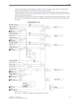
[spannungssymmetrieueberwachung-020313-kn, 1, en_GB]
Figure 2-51
Voltage symmetry monitoring
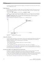
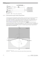
Voltage Phase Sequence
Verification of the faulted phases, phase preference, direction measurement and polarization with quadrature
voltages usually require clockwise rotation of the measured values. The phase rotation of the measuring
voltages is checked by control of the phase sequence of the voltages
U
L1
before U
L2
before U
L3
. This check takes place if each measured voltage has a minimum magnitude of
|U
L1
|, |U
L2
|, |U
L3
| > 40 V/√3
. In case of negative phase rotation, the indication
Fail Ph. Seq.
(No. 171) is displayed.
If the system has a negative phase rotation, this must have been set during the configuration of the power
system data (Section
, address235). In such event, the phase rotation monitoring applies
to the corresponding opposite phase sequence.
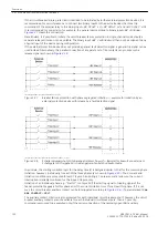
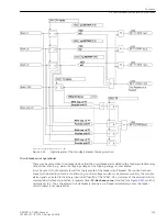
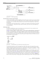
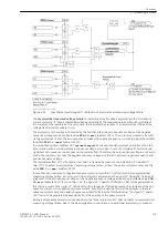
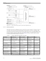
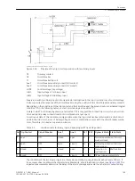
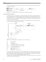
Fast Asymmetrical Measuring Voltage Failure "Fuse Failure Monitor"
In the event of a measured voltage failure due to a short circuit fault or a broken conductor in the voltage
transformer secondary circuit certain measuring loops may mistakenly see a voltage of zero.
If fuses are used instead of a voltage transformer miniature circuit breaker (VT mcb) with connected auxiliary
contacts, then the “Fuse Failure Monitor” can detect problems in the voltage transformer secondary circuit. Of
course, the VT miniature circuit breaker and the “Fuse-Failure-Monitor” can be used at the same time.
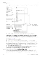
Figures
show the logic of the “fuse-failure monitor”.
Functions
2.7 Monitoring Functions
134
SIPROTEC 4, 7VK61, Manual
C53000-G1176-C159-5, Edition 05.2018
Summary of Contents for SIPROTEC 4 7VK61
Page 8: ...8 SIPROTEC 4 7VK61 Manual C53000 G1176 C159 5 Edition 05 2018 ...
Page 10: ...10 SIPROTEC 4 7VK61 Manual C53000 G1176 C159 5 Edition 05 2018 ...
Page 16: ...16 SIPROTEC 4 7VK61 Manual C53000 G1176 C159 5 Edition 05 2018 ...
Page 176: ...176 SIPROTEC 4 7VK61 Manual C53000 G1176 C159 5 Edition 05 2018 ...
Page 224: ...224 SIPROTEC 4 7VK61 Manual C53000 G1176 C159 5 Edition 05 2018 ...
Page 264: ...264 SIPROTEC 4 7VK61 Manual C53000 G1176 C159 5 Edition 05 2018 ...
Page 270: ...270 SIPROTEC 4 7VK61 Manual C53000 G1176 C159 5 Edition 05 2018 ...
Page 276: ...276 SIPROTEC 4 7VK61 Manual C53000 G1176 C159 5 Edition 05 2018 ...
Page 346: ...346 SIPROTEC 4 7VK61 Manual C53000 G1176 C159 5 Edition 05 2018 ...


