


expected, or if one or more monitoring functions pick up sporadically during normal operation, the sensitivity
settings should be made less sensitive..
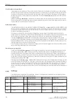
At address 2901
MEASURE. SUPERV
measurement supervision can be switched
ON
or
OFF
.
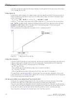
Symmetry monitoring
Address2902
BALANCE U-LIMIT
determines the limit voltage (phase-to-phase), above which the voltage
symmetry monitoring is effective. Address 2903
BAL. FACTOR U
is the associated balance factor, i.e. the
gradient of the balance characteristic. The indication
Fail U balance
(No 167) can be delayed under
address 2908
T BAL. U LIMIT
. These settings can only be changed via DIGSI at Display Additional
Settings.
Address2904
BALANCE I LIMIT
determines the limit current above which the current symmetry monitoring
is effective. Address 2905
BAL. FACTOR I
is the associated balance factor, i.e. the gradient of the balance
characteristic. The indication
Fail I balance
(No 163) can be delayed under address 2909
T BAL. I
LIMIT
. These settings can only be changed via DIGSI at Display Additional Settings.
Sum Monitoring
Address 2906
ΣI THRESHOLD
determines the limit current above which the current sum monitoring is acti-
vated (absolute portion, only relative to
Ι
N
). The relative portion (relative to the maximum phase current) for
activating the current sum monitoring is set at 2907
ΣI FACTOR
. These settings can only be changed via
DIGSI at Display Additional Settings.
i
i
NOTE
Current sum monitoring can operate properly only when the residual current of the protected line is fed to
the fourth current input (
Ι
4
) of the relay.
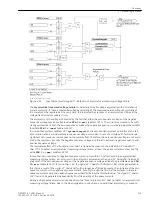
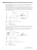
Asymmetrical measuring voltage failure "Fuse Failure Monitor"
The settings for the “fuse failure monitor” for non-symmetrical measuring voltage failure must be selected
such that on the one hand it is reliably activated if a phase voltage fails (address 2911
FFM U>(min)
), but
does not pick up on earth faults in an earthed network on the other hand. Accordingly, address 2912
FFM I<
(max)
(max) must be set sufficiently sensitive (below the smallest fault current during earth faults). These
settings can only be changed via DIGSI at Display Additional Settings.
In address 2910
FUSE FAIL MON.
the “Fuse-Failure-Monitor”, e.g. during asymmetrical testing, can be
switched
OFF
.
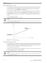
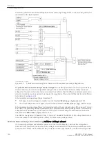
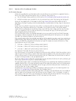
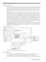
Three-phase measuring-voltage failure "Fuse Failure Monitor"
In address 2913
FFM U<max (3ph)
the minimum voltage threshold is set.If the measured voltage drops
below this threshold and a simultaneous current jump which exceeds the limits according to address 2914
FFM Idelta (3p)
is not detected while all three phase currents are greater than the minimum current
required for the impedance measurement by the distance protection according to address, a three-phase
measured voltage failure is recognized. These settings can only be changed via DIGSI at Display Additional
Settings.
In address 2910
FUSE FAIL MON.
the “Fuse-Failure-Monitor”, e.g. during asymmetrical testing, can be
switched
OFF
.
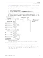
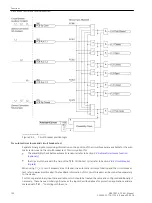
Measured voltage failure monitoring
The measured voltage failure monitoring can be switched under address 2915
V-Supervision
w/
CURR.SUP
,
w/ I> & CBaux
or
OFF
. Address 2916
T V-Supervision
is used to set the waiting time of the
voltage failure supervision. This setting can only be changed in DIGSI at Display Additional Settings.
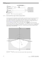
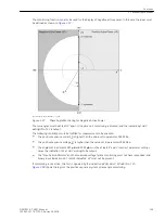
Monitoring the phase angle of the positive sequence power
The parameters 2943
I1>
and 2944
U1>
are used to specify the minimum positive sequence system quanti-
ties required for measurement of the positive sequence power. The angles set in address 2941
φA
and 2942
Functions
2.7 Monitoring Functions
142
SIPROTEC 4, 7VK61, Manual
C53000-G1176-C159-5, Edition 05.2018
Summary of Contents for SIPROTEC 4 7VK61
Page 8: ...8 SIPROTEC 4 7VK61 Manual C53000 G1176 C159 5 Edition 05 2018 ...
Page 10: ...10 SIPROTEC 4 7VK61 Manual C53000 G1176 C159 5 Edition 05 2018 ...
Page 16: ...16 SIPROTEC 4 7VK61 Manual C53000 G1176 C159 5 Edition 05 2018 ...
Page 176: ...176 SIPROTEC 4 7VK61 Manual C53000 G1176 C159 5 Edition 05 2018 ...
Page 224: ...224 SIPROTEC 4 7VK61 Manual C53000 G1176 C159 5 Edition 05 2018 ...
Page 264: ...264 SIPROTEC 4 7VK61 Manual C53000 G1176 C159 5 Edition 05 2018 ...
Page 270: ...270 SIPROTEC 4 7VK61 Manual C53000 G1176 C159 5 Edition 05 2018 ...
Page 276: ...276 SIPROTEC 4 7VK61 Manual C53000 G1176 C159 5 Edition 05 2018 ...
Page 346: ...346 SIPROTEC 4 7VK61 Manual C53000 G1176 C159 5 Edition 05 2018 ...


