background image

08.96

Options

Siemens AG    6SE7087-6BM70

6-9

SIMOVERT MASTER DRIVES    Operating Instructions

6.6 

Bypass- and output contactor

6.6.1 

Bypass contactor (electrical DC link
coupling)

Using the electrical DC link coupling, it is possible, for a
multi-motor group with common DC bus, to connect or
disconnect a converter with DC supply input to the DC
bus.

This option is used when an inverter section has to be
replaced.

Binary output -X9:4,5 is provided to control the contactor.

6.6.1.1 

Bypass contactor without I/R unit

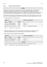
Parameterization for operation with bypass contactor:

Parameter-

Terminal

No.

Name

Value

P612, i001 ST. MC energized

0000

X9: 4,5

P629, i001 ST.BC energized

1001

X9: 4,5

Table 6.11

Parameterization for the bypass contactor

(electrical DC link coupling)

-X1 C/

L+

D/
L-

DC24 V

Auxiliary voltage
bypass contactor

Electrical DC
link coupling

-X2

C/L+

D/L-

-K10

-K10

1 2

-X9

U2/
T1

V2/
T2

W2/
T3

-X9:4

-X9:5

M

3

Fig. 6.6

Connecting-up example for the bypass contactor

Summary of Contents for simovert master drive

Page 1: ...SIMOVERT MASTER DRIVES Operating Instructions Part 1 Types J to M DC AC Edition AB Order No 6SE7087 6BM70 ...

Page 2: ...ructions consists of Part 1 Part 2 6SE708_ _AD10 6SE708_ _AD70 6SE708_ _XX10 6SE708_ _AD20 6SE708_ _AD70 6SE708_ _XX20 6SE708_ _AD30 6SE708_ _AD70 6SE708_ _XX30 6SE708_ _BD10 6SE708_ _BD70 6SE708_ _XX10 6SE708_ _BD20 6SE708_ _BD70 6SE708_ _XX20 6SE708_ _BD30 6SE708_ _BD70 6SE708_ _XX30 6SE708_ _AH10 6SE708_ _AH70 6SE708_ _XX10 6SE708_ _AH20 6SE708_ _AH70 6SE708_ _XX20 6SE708_ _AH30 6SE708_ _AH70 6...

Page 3: ...Transport and unpacking 2 1 2 2 Storage 2 1 2 3 Mounting 2 2 2 4 Dimension drawings 2 4 3 Connecting up 3 1 3 1 Power connections 3 2 3 1 1 Protective conductor connection 3 4 3 2 Auxiliary power supply main contactor or bypass contactor 3 4 4 Operator control 4 1 4 1 Operator control elements 4 1 4 2 Displays 4 2 5 Maintenance 5 1 5 1 Maintenance requirements 5 1 5 2 Replacing components 5 2 5 2 ...

Page 4: ...s 6 3 6 3 Power supplies 6 3 6 4 Isolating amplifiers 6 4 6 5 Power section 6 4 6 5 1 Output reactor dv dt filter 6 5 6 5 1 1 Output reactor 6 6 6 5 1 2 dv dt filter 6 7 6 5 1 3 Selection criteria for the output reactor or dv dt filter 6 8 6 6 Bypass and output contactor 6 9 6 6 1 Bypass contactor electrical DC link coupling 6 9 6 6 1 1 Bypass contactor without I R unit 6 9 6 6 1 2 Bypass contacto...

Page 5: ...12 96 General Siemens AG 6SE7087 6BM70 0 5 SIMOVERT MASTER DRIVES Operating Instructions 10 Appendix 10 1 10 1 Index 10 1 10 2 List of abbreviations 10 2 11 Addresses 11 1 12 Certificates 12 1 ...

Page 6: ...e can result if proper precautions are not taken CAUTION For the purpose of these instructions and product labels Caution indicates that minor personal injury or material damage can result if proper precautions are not taken NOTE For the purpose of these instructions Note indicates information about the product or the respective part of the Instruction Manual which is essential to highlight NOTE T...

Page 7: ...ts should only be stored and transported in conductive packaging e g metalized plastic boxes metal containers If the packing material is not conductive the boards must be wrapped with a conductive packaging material e g conductive foam rubber or household aluminum foil The necessary ECB protective measures are clearly shown in the following diagram a Conductive floor surface d ESD overall b ESD ta...

Page 8: ...ng of the drive converter i e the starting of normal operation is prohibited until the machinery has been proved to conform to the provisions of the directive 89 392 EEC Machinery Safety Directive MSD Account is to be taken of EN 60204 Commissioning i e the starting of normal opertion is admissible only where conformity with the EMC directive 89 336 EEC has been established The drive converters me...

Page 9: ...f the limit values required by EMC law is the responsibility of the manufacturer of the installation or machine 6 Operation Installations which include drive converters shall be equipped with additional control and protective devices in accordance with the relevant applicable safety requirements e g Act respecting technical equipment accident prevention rules etc Changes to the drive converters by...

Page 10: ......

Page 11: ...d to continuously control the speed of three phase motors SIMOVERT MASTER DRIVES can be used with a common DC link as well as for single motor and multi motor drives Technological functions and expansions can be realized via defined interfaces in the open loop control section 1 2 Mode of operation Converters with DC current input are suitable for coupling several converters to a common DC link bus...

Page 12: ...r multi motor drives the motors within the group must be the same Some of the applications are for example Winder drives Rolling mill drives When the drive is shipped closed loop V f control is preset Closed loop frequency control with field oriented vector control must be parameterized The converter can be set as a result of the precise motor simulation up to a maximum frequency of 300 Hz with an...

Page 13: ...ting Instructions 1 4 Block diagram Motor connection U2 T1 V2 T2 W2 T3 PE2 Inverter with CU and PMU CU P Connector for OP1 Terminal strip Option boards in the elec tronics box C L D L PE1 Fusing and DC link DC bus connection Fig 1 1 Block diagram types of construction J and K ...

Page 14: ...tor connection U2 T1 V2 T2 W2 T3 Inverter with CU and PMU C L D L Fusing and DC link DC bus connection Inverter with CU and PMU CU P Connector for OP1 Terminal strip Option boards in the elec tronics box Fusing and DC link PE1 PE1 PE2 PE2 Master Slave Fig 1 2 Block diagram type of construction M ...

Page 15: ...ng on the degree of protection and type of construction the units may be mounted on a pallet either with or without transport rails Degree of prot IP00 Pallet Type of construction J one unit Type of construction K one unit Type of construction M three units master drive converter type of construction K reactor slave drive converter type of construction K without electronics box Degree of prot IP20...

Page 16: ...rotection against direct contact It is the users responsibility to ensure and provide the correct protection against contact according to the relevant accident prevention regulations VBG4 by appropriately designing the enclosure or enclosures around the chassis unit Remove shipping brace marked The three units type of construction M with degree of protection IP00 must be assembled according to the...

Page 17: ... laden air must be filtered WARNING When mounting in cabinets a clearance of above and below must be provided so that the cooling air flow is not restricted refer to dimension drawings Section 2 4 Dimension the cabinet cooling in line with the power loss Section Technical data The converter ambient climate in operating rooms may not exceed the values of code F according to DIN 40040 For temperatur...

Page 18: ...270 kg 1 Connection for 4 x 300 mm 2 Protective conductor 4 x 300 mm to the rectifier regenerative feedback unit Detail X to the DC busbar ø13 5 M 12 DC connection in accordance with DIN 43673 with 6 x 60 mm copper bar 26 17 26 17 Elongated hole 9x12 U 139 83 ca 710 213 483 708 x 2 1 V W Electronics box Fan assembly must be removed to disassemble the unit DC positive DC negative 1400 5 1345 67 668...

Page 19: ...26 17 X DC AC chassis unit Type of construction 6SE70 IP00 1 Connection for 4 x 300 mm 2 Protective conductor 4 x 300 mm Net weight approx 250 kg With transport parts approx 540 kg to the rectifier regenerative feedback unit Detail X to the DC busbar DC connection in accordance with DIN 43673 with 6 x 60 mm copper bar Elongated hole 9x12 Electronics box Fan assembly must be removed to disassemble ...

Page 20: ...onnection output 8 x 240 mm C Cable duct for control cables from the Master to the Slave View without cover 10460 10470 View without side panel Divided cover Bottom cover transparent Cover including bolt head 1 Painted transport rail 2 Only in the side panel left 3 Cut out in the rear panel Top cover transparent Fig 2 3 Reactor chassis Type of construction M ...

Page 21: ...8 10 121 10 730 240 100 600 5 10 mm thick 10 mm thick 730 100 50 25 45 15 50 50 50 100 25 W eight IP00 1200 kg IP20 1550 kg SIMOVERT MASTER DRIVES Inverter Components frame size M 12 Master slave reactor chassis mounted in a cabinet frame 8MC 13 1975 85 1880 25 589 40 20 45 28 89 1 7 C D connecting lugs alternatively 4 x cable lugs directly at the C D bus max 4 x 240 mm 13 mm diameter hole or M12 ...

Page 22: ... D Master WR Reactor Slave WR Fan assembly Fan assembly U V W Incoming fuses F11 F12 F21 F22 Elektronics box with PMU Cabinet frame Incoming fuse F11 F12 F21 F22 U V W SIMOVERT MASTER DRIVES Inverter Components frame size M 12 Master slave reactor chassis mounted in a cabinet frame 8MC Fig 2 5 Type of construction M ...

Page 23: ... capacitors must be formed at start up if the unit has been stored for a longer period of time Forming is described in the Instruction Manual Part 2 When the DC link is supplied from a central unit it must be ensured that the converter is reliably isolated from the DC link voltage The user is responsible that the motor converter and any other associated devices or units are installed and connected...

Page 24: ...drawings Section 2 4 DC connection C L D L Motor connection U2 T1 V2 T2 W2 T3 Protective conductor connection PE1 PE2 The power connections should be established using cable lugs with screws according to Table 3 2 For type of construction J jumpers are inserted after the inverter connections which can be replaced by fuses For drive converters type of construction K fuses are installed as standard ...

Page 25: ...00 41 2UM20 1464 6 300 6 800 2 500 2 3NE3334 0B 2 170M5712 660 2 630 1230 6 800 6 800 41 4UM20 1666 6 300 6 800 2 630 2 3NE3336 2 170M6712 660 2 800 1400 6 800 6 800 41 6UM20 1880 8 300 8 800 2 630 2 3NE3336 2 170M6712 660 2 800 1580 6 800 6 800 Input voltage DC 890 V to 930 V Output voltage 3 AC 0 V to 930 V 33 0WJ20 354 2 300 2 800 1 500 3NE3334 0B 170M5713 660 700 297 2 300 2 800 33 5WJ20 421 2...

Page 26: ...terminal strip Cables from 0 2 mm2 to 2 5 mm2 AWG 24 to 14 can be connected to X9 The auxiliary power supply is required if the drive converter is fed through a main and bypass contactor The main or monitoring contactor is controlled through floating contacts X9 4 and X9 5 software pre setting More detailed information is provided in the Section options Term Function description 1 Types of constru...

Page 27: ...ion Converter switch on standard For faults Return to the fault display Command is effective when the key is released Converter shutdown depending on the parameterization of OFF 1 OFF 2 or OFF 3 P554 to P560 Command becomes effective when the key is released Field reversal reversing for the appropriate parameterization Command becomes effective when the key is released P Changeover from parameter ...

Page 28: ...tual value e g e g e g Visualization parameters Basic converter Technology board Setting parameters Basic converter Technology board Table 4 2 Displaying visualization and setting parameters on the PMU Actual value Parameter value not possible Alarm Fault Display Table 4 3 Status display on the PMU NOTE The parameter description is provided in the Operating Instructions Part 2 ...

Page 29: ...d test equipment and protective clothing always stand on an ungrounded isolated and ESD compatible pad If these warnings are not observed this can result in death severe bodily injury or significant material damage Always have your MASTER DRIVE converter Order No and serial No available when contacting the service department These numbers and other important data are located on the drive converter...

Page 30: ...fan assembly For type of construction K with one fan the air deflection plate below the fan must be disassembled 2 M8 Withdraw the fan assembly towards the front and if required tilt it gently downwards and place carefully on a flat surface CAUTION The fan assembly can weigh up to 38 kg depending on the drive converter rating Remove the cable ties and fan connections Remove the fan mounting panel ...

Page 31: ...oards Each board has a capacitor mounting element and a DC link bus connection Remove the plug connections Release the mechanical retaining elements three screws two at the left one at the right Remove the capacitor by slightly raising them and withdrawing them from the drive converter towards the front CAUTION The capacitors weight up to 30 kg depending on the drive converter rating Install a new...

Page 32: ...s M8 torque 8 10 Nm tighten up the M6 nut on the distance studs 6 Nm connect up the snubber resistors M4 bolts torque max 1 8 Nm tighten up the power connections M8 bolts torque 13 Nm remove the template from the module busbars 5 2 6 1 Replacing the balancing resistor The balancing resistor is located at the rear mounting plane on the heatsink between the inverter modules i e behind the capacitors...

Page 33: ...onductive grounded object immediately beforehand e g bare metal cubicle components 5 2 7 1 Replacing the IVI IPI type of construction M IVI Inverter Value Interface IPI Inverter Parallel Interface for type of construction M The IVI IPI is bolted to the rear of the electronics box Remove the electronics module to the endstop Remove the ground connection at the electronics module Remove all boards f...

Page 34: ...e VDU mounting panel Release the plug connections on the PSU Release the bolts six Torx M4 on the PSU Remove the PSU Install the new PSU in the inverse sequence 5 2 7 4 Replacing the IGD IGD IGBT Gate Drive The IGD is located behind the module busbars and consists of one board for type of construction J three boards for type of construction K Remove the capacitors Remove SML and SMU Remove the mod...

Page 35: ...he new snubber resistor in the inverse sequence 5 2 8 1 Replacing the IGBT modules Replace as for IGD but additionally Remove the mounting bolts of the defective IGBT modules and remove the IGBT Install the new IGBT module Observe the following Coat the module mounting surface with a thin and uniform coating of heat conducting paste Tighten up the IGBT module mounting bolts with 3 Nm observe the s...

Page 36: ...ghten the retaining screws above and below the handles 5 2 8 3 Replacing the PMU Parameterization Unit Remove the ground cable at the side panel Carefully depress the snap on the adapter section and remove the PMU with adapter section from the electronics box Withdraw connector X108 on the CU Carefully withdraw the PMU board out of the adapter section towards the front using a screwdriver Install ...

Page 37: ...ert the CU into the lefthand slot screw the retaining screws on the handles tight and insert the connecting cable to the PMU Insert the option board in slot 2 right or slot 3 center of the electronics box and screw into place Each option board may only by inserted in the electronics box If only one option is used it must always be inserted at slot 2 right Slots in the electronics box Boards Left S...

Page 38: ...ications board for peer to peer connection and USS protocol via RS485 Use of the serial interface with USS protocol Board description Application description 6SE7090 0XX84 0BD0 6SE7087 6CX84 0BD0 6SE7087 6CX87 4KB0 CB1 Communications board with interface for SINEC L2 DP Profibus Use of the PROFIBUS DP interface Board description Application description 6SE7090 0XX84 0AK0 6SE7087 6CX84 0AK0 6SE7087...

Page 39: ...inputs and outputs for coupling to the SCB1 via fiber optic cable Board description 6SE7090 0XX84 3EF0 6SE7087 6CX84 0BC0 DTI Digital tachometer interface Board description 6SE7090 0XX84 3DB0 6SE7087 6CX84 3DB0 ATI Analog tachometer interface Board description 6SE7090 0XX84 3DF0 6SE7087 6CX84 3DF0 Table 6 4 Interface boards 6 3 Power supplies Designation Description Order number Option Use with Po...

Page 40: ...verview of isolating amplifiers 6 5 Power section Options Description function Braking unit For converting the regenerative energy into heat Braking resistors Load resistor for the braking unit Electrical DC link coupling Switching the DC AC converter in and out under load Mechanical DC link coupling Switching the DC AC converter in and out in a no voltage condition Input rectifier Input rectifier...

Page 41: ... 1 2 3 4 500 1000 1460 1500 t µs for motors in accordance with IEC 34 17 1992 DIN VDE 0530 Part1 Sheet2 V for Siemens 1LA2 1LA5 1LA6 and 1LA8 motors Standard 1LA8 motors 1LA8 motors with improvedinsulation are available Depending on the application the voltagerate of rise voltage and current peaks can be reduced using the following options Output reactor dv dt filter Characteristics of the output ...

Page 42: ...stant 510 V to 620 V DC 675 V to 930 V DC 510 V to 620 V DC 675 V to 930 V DC Standard reactor iron fP 3 kHz V f Vector control fmot N 87 Hz fmot N 200 Hz fmax 200 Hz fmax 300 Hz V f textile fmot N fmax 120 Hz not possible not possible not possible Ferrite reactor fP 6 kHz V f Vector control fmot N 150 Hz fmax 300 Hz V f textile fmot N fmax 600 Hz not possible Table 6 9 Output reactor design 1 out...

Page 43: ... Control and VC Vector Control The dv dt filter is suitable for use with grounded supply networks TN and TT supply networks ungrounded supplies IT supplies exceptions 6SE70_ _ _ _ B _ _ 1FD0 and 6SE70 _ _ _ _ C _ _ 1FD0 with version release A NOTE The dv dt filter is designed for a pulse frequency fp 3 kHz and an output frequency fA 300 Hz In this case when the drive converter is being set P052 5 ...

Page 44: ... motor cable lengths output reactors are required in accordance with Section Output reactor Fig 6 4 dv dt filter required Cable lengths in accordance with the Section dv dt filter Fig 6 5 dv dt filter required Cable lengths in accordance with the Section dv dt filter Fig 6 5 Siemens motors 1LA8 2 An output filter is not required For longer motor cable lengths output reactors are required in accord...

Page 45: ...nverter section has to be replaced Binary output X9 4 5 is provided to control the contactor 6 6 1 1 Bypass contactor without I R unit Parameterization for operation with bypass contactor Parameter Terminal No Name Value P612 i001 ST MC energized 0000 X9 4 5 P629 i001 ST BC energized 1001 X9 4 5 Table 6 11 Parameterization for the bypass contactor electrical DC link coupling X1 C L D L DC24 V Auxi...

Page 46: ...e feedback unit During commissioning the following steps are required Re parameterization for the optimization run Parameter Terminal Information No Name Value P629 i001 ST BC energized 0000 X9 4 5 P612 i001 ST BC energized 1001 X9 4 5 P600 i001 ST ready to switch on 1001 X9 4 5 Bypass contactor closes Table 6 12 Parameterization for the optimization run Execute the optimization run to determine t...

Page 47: ...erters to the bus 6 6 2 Output contactor It is not necessary that the converter is operated with output contactor If the converter is operated with output contactor binary output X9 4 5 is provided for contactor control re assignment The checkback signal can be connected to a binary input e g binary input 3 Sequence control on command operation effect on the bypass or output contactor NOTES For th...

Page 48: ...ng Instructions 6 7 Operator control Option Description OP1 User friendly operator control panel with plain text display SIMOVIS Floppy disk with program for operator control via PC Table 6 15 Operator control options P Fault Run 0 Reset 1 2 3 6 5 4 7 8 9 Jog O I Fig 6 8 OP1 ...

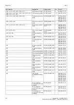
Page 49: ... fan 6SY7000 0AB65 4 6SE7041 3TM20 A10 U1 F101 F102 A12 U1 F101 F102 Fused load disconnector 6SY7000 0AA26 4 6SE7041 1TM20 6SE7041 3TM20 A10 U1 F101 F102 A12 U1 F101 F102 Fuse insert 6SY7000 0AC34 4 6SE7041 1TM20 6SE7041 3TM20 A10 U1 F41 F42 F43 F44 A12 U1 F41 F42 F43 F44 Fuse insert 6SY7000 0AB75 8 6SE7041 1TM20 6SE7041 3TM20 A10 U1 R100 R200 R300 A12 U1 R100 R200 R300 Balancing resistor 6SY7000 ...

Page 50: ...face board 6SE7038 6GL84 1BG0 1 6SE7035 1TJ20 6SE7036 0TK20 6SE7037 0TK20 6SE7038 6TK20 A20 IVI inverter interface board 6SE7038 6GL84 1BG2 1 6SE7041 1TK20 A22 IPI parallel switching board 6SE7090 0XX84 1CE0 1 6SE7041 1TM20 6SE7041 3TM20 A25 ABI normalization board 6SE7041 1TM84 1CF0 1 6SE7041 1TM20 A25 ABI normalization board 6SE7041 3TM84 1CF0 1 6SE7041 3TM20 A26 ABO normalization board 6SE7035 ...

Page 51: ...TK20 6SE7038 6TK20 6SE7041 1TK20 F101 F102 Fuse insert 6SY7000 0AC34 2 6SE7035 1TJ20 6SE7036 0TK20 6SE7037 0TK20 6SE7038 6TK20 F101 F102 Fuse insert 6SY7000 0AC42 2 6SE7041 1TK20 F41 F42 F43 F44 Fuse insert 6SY7000 0AB75 4 6SE7036 0TK20 6SE7037 0TK20 6SE7035 1TJ20 F41 F42 F43 F44 Fuse insert 6SY7000 0AB88 4 6SE7038 6TK20 F41 F42 F43 F44 Fuse insert 6SY7000 0AC64 4 6SE7041 1TK20 R100 R200 R300 Bala...

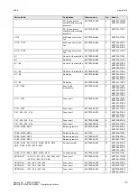
Page 52: ...A310 A311 IGBT transistor module 6SY7000 0AC37 24 6SE7041 4UM20 6SE7041 6UM20 A10 U1 A118 A119 A218 A219 A318 A319 A12 U1 A118 A119 A218 A219 A318 A319 SML3 inverter snubber board 6SE7038 6GK84 1GG0 12 6SE7041 0UM20 6SE7041 1UM20 6SE7041 2UM20 6SE7041 4UM20 6SE7041 6UM20 A10 U1 A19 A29 A39 A12 U1 A19 A29 A39 IGD8 inverter gating board 6SE7035 7GK84 1JC0 6 6SE7041 0UM20 6SE7041 1UM20 A10 U1 A19 A29...

Page 53: ...041 4UM20 6SE7041 6UM20 A10 U1 R100 R200 R300 A12 U1 R100 R200 R300 Balancing resistor 6SY7000 0AA77 6 6SE7041 0UM20 6SE7041 1UM20 6SE7041 2UM20 A10 U1 R100 R200 R300 A12 U1 R100 R200 R300 Balancing resistor 6SY7000 0AA76 6 6SE7041 4UM20 6SE7041 6UM20 A10 U1 R108 R109 R118 R119 R208 R209 R218 R219 R308 R309 R318 R319 A12 u1 r108 r109 r118 r119 r208 r209 r218 r219 r308 r309 r318 r319 Snubber resist...

Page 54: ...SE7034 5UK20 6SE7035 7UK20 6SE7036 5UK20 6SE7038 6UK20 A109 A209 A309 SMU3 inverter snubber board 6SE7038 6GK84 1GF0 3 6SE7033 0UJ20 6SE7033 5UJ20 A118 A119 A218 A219 A318 A319 SML3 inverter snubber board 6SE7038 6EK84 1GG0 6 A118 A119 A218 A219 A318 A319 SML3 inverter snubber board 6SE7038 6GK84 1GG0 6 6SE7034 5UK20 6SE7035 7UK20 6SE7036 5UK20 6SE7038 6UK20 A119 A219 A319 SML3 inverter snubber bo...

Page 55: ...r gating board 6SE7033 5GJ84 1JC0 1 6SE7033 0UJ20 6SE7033 5UJ20 A30 PMU operator control parameterizing unit 6SE7090 0XX84 2FA0 1 6SE7033 0UJ20 6SE7033 5UJ20 6SE7034 5UK20 6SE7035 7UK20 6SE7036 5UK20 6SE7038 6UK20 6SE7041 0UM20 6SE7041 1UM20 6SE7041 2UM20 6SE7041 4UM20 6SE7041 6UM20 DC link capacitors complete with mounting assembly 6SY7000 0AC27 3 6SE7034 5UK20 DC link capacitors complete with mo...

Page 56: ...5UK20 6SE7038 6UK20 F101 F102 Fuse insert 6SY7000 0AC34 2 6SE7033 0UJ20 6SE7033 5UJ20 6SE7034 5UK20 6SE7035 7UK20 6SE7036 5UK20 F101 F102 Fuse insert 6SY7000 0AC42 2 6SE7038 6UK20 F41 F42 Fuse insert 6SY7000 0AB87 2 6SE7033 0UJ20 F41 F42 Fuse insert 6SY7000 0AB74 2 6SE7033 5UJ20 F41 F42 Fuse insert 6SY7000 0AB88 2 6SE7034 5UK20 F41 F42 F43 F44 Fuse insert 6SY7000 0AB77 4 6SE7035 7UK20 F41 F42 F43 ...

Page 57: ... No Designation Order No No Used in A10 U1 A100 A101 A110 A111 A200 A201 A210 A211 A300 A301 A310 A311 A12 U1 A100 A101 A110 A111 A200 A201 A210 A211 A300 A301 A310 A311 IGBT transistor module 6SY7000 0AB71 24 6SE7041 0WM20 6SE7041 1WM20 A10 U1 A100 A101 A110 A111 A200 A201 A210 A211 A300 A301 A310 A311 A12 U1 A100 A101 A110 A111 A200 A201 A210 A211 A300 A301 A310 A311 IGBT transistor module 6SY70...

Page 58: ...E7041 6WM20 A10 U1 F101 F102 A12 U1 F101 F102 Fuse insert 6SY7000 0AC34 4 6SE7041 0WM20 6SE7041 1WM20 6SE7041 2WM20 A10 U1 F101 F102 A12 U1 F101 F102 Fuse insert 6SY7000 0AC42 4 6SE7041 4WM20 6SE7041 6WM20 A10 U1 F41 F42 F43 F44 A12 U1 F41 F42 F43 F44 Fuse insert 6SY7000 0AB77 8 6SE7041 0WM20 6SE7041 1WM20 A10 U1 F41 F42 F43 F44 A12 U1 F41 F42 F43 F44 Fuse insert 6SY7000 0AB87 8 6SE7041 2WM20 A10 ...

Page 59: ...11 A200 A201 A210 A211 A300 A301 A310 A311 IGBT transistor module 6SY7000 0AC37 12 6SE7038 6WK20 A100 A110 A200 A210 A300 A310 IGBT transistor module 6SY7000 0AC36 6 6SE7033 0WJ20 A100 A110 A200 A210 A300 A310 IGBT transistor module fz1200r16kf1 1200a 1600v 6SY7000 0AB14 6 6SE7033 5WJ20 A108 A109 A208 A209 A308 A309 SMU3 inverter snubber board 6SE7038 6GK84 1GF0 6 6SE7034 5WK20 6SE7035 7WK20 6SE70...

Page 60: ...26 ABO normalization board 6SE7035 7WK84 1BH0 1 6SE7035 7WK20 A26 ABO normalization board 6SE7036 5WK84 1BH0 1 6SE7036 5WK20 A26 ABO normalization board 6SE7038 6UK84 1BH0 1 6SE7038 6WK20 A28 VDU voltage divider board 6SE7038 6GL84 1JB0 1 6SE7033 0WJ20 6SE7033 5WJ20 6SE7034 5WK20 6SE7035 7WK20 6SE7036 5WK20 6SE7038 6WK20 A29 IGD7 inverter gating board 6SE7033 5GJ84 1JC0 1 6SE7033 0WJ20 6SE7033 5WJ...

Page 61: ...4 5WK20 6SE7035 7WK20 6SE7036 5WK20 E1 E2 Radial fan 6SY7000 0AB68 2 6SE7034 5WK20 6SE7035 7WK20 6SE7036 5WK20 E1 E2 Nozzle for the radial fan 6SY7000 0AC41 2 6SE7041 4WM20 6SE7041 6WM20 F101 F102 Fused load disconnector 6SY7000 0AA26 2 6SE7033 0WJ20 6SE7033 5WJ20 6SE7034 5WK20 6SE7035 7WK20 6SE7036 5WK20 6SE7038 6WK20 F101 F102 Fuse insert 6SY7000 0AC34 2 6SE7033 0WJ20 6SE7033 5WJ20 6SE7034 5WK20...

Page 62: ...WK20 OPTION L31 A10 U1 F41 F42 F43 F44 A12 U1 F41 F42 F43 F44 Fuse insert 6SY7000 0AC16 8 6SE7041 0WM20 6SE7041 1WM20 6SE7041 2WM20 OPTION L31 A10 U1 F41 F42 F43 F44 A12 U1 F41 F42 F43 F44 Fuse insert 6SY7000 0AC20 8 6SE7041 4WM20 6SE7041 6WM20 OPTION L31 F41 F42 Fuse insert 6SY7000 0AC17 2 6SE7033 0WJ20 6SE7033 5WJ20 6SE7034 5WK20 OPTION L31 F41 F42 F43 F44 Fuse insert 6SY7000 0AC16 4 6SE7035 7WK...

Page 63: ...retrofit PS Fan housing UP Tensioning profile retaining bolts Halogen containing flame retardants were for all essential components replaced by environmentally friendly flame retardants Environmental compatibility was an important criterium when selecting the supplied components Environmental aspects during production Purchased components are generally supplied in recyclable packaging materials bo...

Page 64: ......

Page 65: ...nvironmental class 3K3 DIN IEC 721 3 3 Moisture condensation not permissible Pollution level 2 DIN VDE 0110 Pert 1 Overvoltage category III DIN VDE 0110 Part 2 Overvoltage property class 1 E DIN VDE 0160 Protection class I DIN VDE 0106 Section 1 Radio interference level standard without DIN VDE 0875 Section 11 EN 55011 Noise immunity EN50082 2 Mechanical strength DIN IEC 68 2 6 06 90 Frequency ran...

Page 66: ...AC 230 15 Loading Class II acc to EN 60146 1 1 Rated current A 464 538 628 783 1001 1001 1183 Base load time s 240 Overcurrent A 694 802 938 1169 1496 1496 1768 Overcurrent time s 60 Losses cooling power factor Power factor Converter cosϕU 0 92 ind 0 92 ind 0 92 ind 0 92 ind 0 92 ind 0 92 ind 0 92 ind Efficiency η Pulse frequency 2 5 kHz 0 98 0 98 0 98 0 98 0 98 0 98 0 98 Power loss Pulse frequenc...

Page 67: ...y V AC 230 15 Loading Class II acc to EN 60146 1 1 Rated current A 270 322 411 519 591 783 Base load time s 240 Overcurrent A 404 481 614 775 884 1170 Overcurrent time s 60 Losses cooling power factor Power factor Converter cosϕU 0 92 ind 0 92 ind 0 92 ind 0 92 ind 0 92 ind 0 92 ind Efficiency η Pulse frequency 2 5 kHz 0 98 0 98 0 98 0 98 0 98 0 98 Power loss Pulse frequency 2 5 kHz kW 5 6 6 6 7 7...

Page 68: ...ry power supply V AC 230 15 Loading Class II acc to EN 60146 1 1 Rated current A 901 983 1119 1274 1438 Base load time s 240 Overcurrent A 1346 1469 1673 1904 2149 Overcurrent time s 60 Losses cooling power factor Power factor Converter cosϕU 0 92 ind 0 92 ind 0 92 ind 0 92 ind 0 92 ind Efficiency η Pulse frequency 2 5 kHz 0 98 0 98 0 98 0 98 0 98 Power loss Pulse frequency 2 5 kHz kW 14 17 21 25 ...

Page 69: ...y V AC 230 15 Loading Class II acc to EN 60146 1 1 Rated current A 270 322 411 519 591 783 Base load time s 240 Overcurrent A 404 481 614 775 884 1170 Overcurrent time s 60 Losses cooling power factor Power factor Converter cosϕU 0 92 ind 0 92 ind 0 92 ind 0 92 ind 0 92 ind 0 92 ind Efficiency η Pulse frequency 2 5 kHz 0 98 0 98 0 98 0 98 0 98 0 98 Power loss Pulse frequency 2 5 kHz kW 5 8 7 0 7 9...

Page 70: ...y power supply V AC 230 15 Loading Class II acc to EN 60146 1 1 Rated current A 901 983 1119 1274 1438 Base load time s 240 Overcurrent A 1346 1469 1673 1904 2149 Overcurrent time s 60 Losses cooling power factor Power factor Converter cosϕU 0 92 ind 0 92 ind 0 92 ind 0 92 ind 0 92 ind Efficiency η Pulse frequency 2 5 kHz 0 98 0 98 0 98 0 98 0 98 Power loss Pulse frequency 2 5 kHz kW 16 20 23 9 29...

Page 71: ...evel For installation altitudes 1000 m above sea level the rated current must be reduced For installation altitudes 2000 m above sea level the rated voltage must be reduced see Fig 9 2 Installation altitudes 4000 m above sea level are not permissible permissible rated current in 100 90 80 60 500 1000 2000 installation altitude in m 3000 4000 70 permissible rated voltage in 100 90 80 60 500 1000 20...

Page 72: ......

Page 73: ...ss 8 1 I Interface boards 6 3 Isolating amplifiers 6 4 M Maintenance 5 1 Maintenance requirements 5 1 Mode of operation 1 1 Mounting 2 2 O Operator control 4 1 6 12 Operator control elements 4 1 Options 6 1 Options which can be integrated into the electronics box 6 1 Output contactor 6 11 Output reactor 6 6 Output reactor dv dt filter 6 5 P Power connections 3 2 Power section 6 4 Power supplies 6 ...

Page 74: ...ated circuit ASM Asynchronous motor ATI Analog tacho Interface AWG American wire gauge BA Binary output BC Bypass contactor BE Binary input BF Type of construction CAN Controller area network CB Communication board option CU Control unit CUA Control unit AFE control unit of AFE DC Direct current DPR Dual port RAM DPRAM Dual port RAM EA First run up EEPROM Electrically erasable programmable read on...

Page 75: ...ng L Low binary signal level LBA Local bus adapter option LED Light emitting diode LSB Least significant bit MC Main contactor MDS Motor data set MLFB Machine readable product designation machine readable designation MSB Most significant bit NN Sea level OP 1 Operation panel 1 Par Parameter PC Personal computer PEU Power electronic unit PG Programming unit programmer PKW Parameter ID value PMU Par...

Page 76: ...tion TLG Telegram TRC Trace TSY Tacho and synchronization option TTL Transistor Transistor Logic UCE Voltage V collector emitter desaturation signal of the transistors UMR Drive converter USS Universal serial interface VC Vector control control version of SIMOVERT MASTER DRIVES VDU Voltage dividing unit VS Precharging contactor Vsa Line supply voltage components in the a axis Vsb Line supply volta...

Page 77: ...svall SWITZERLAND Siemens Albis AG Zürich Basel Renens Lausanne SLOWAKIAN REP Siemens s r o Bratislava SLOVENIA Siemens d o o Ljubljana SPAIN Siemens S A Madrid CZECHIA REP Siemens s r o Praha Brno TURKEY SIMKO Ticaret ve Sanayi A S Istanbul Adana Ankara Bursa Izmir Samsun UKRAINE Vertretung der Siemens AG Kiew HUNGARIAN Siemens kft Budapest CYPRUS Jolali Ltd Nicosia World Africa EGYPT Siemens Tec...

Page 78: ...ONG Siemens Ltd Hong Kong INDIA Siemens Limited Bombay Ahmedabad Bangalore Calcutta Madras New Delhi Secunderabad Thane INDONESIA Representative Siemens AG Jakarta P T Dian Graha Elektrika Jakarta IRAN Siemens S S K Teheran JAPAN Siemens K K Tokyo JEMEN Tihama Tractors Engineering Co Ltd Sanaa Aviation Engineering Agency Aden JORDAN A R Kevorkian Co Amman F A Kettaneh Co Ltd Amman SOUTH KOREA Siem...

Page 79: ... part1 IV RUN IN Ambient temperature Duration Scampling 55 C cycled 24 up to 72 hours 10 to 100 Test results are documented within the production data file ASI 1 PE D F Schlögel ASI 1 Drive Technology Drive and Standard Products Group Test certificate Equipment Order No The routine testing according to these test instructions checking of presence of all components acc to parts list power supply cu...

Page 80: ...ly when replacing any part component All panels must be closed during operation is manufactured in conformance with DIN VDE 0558 Part 2and DIN VDE 0113 Part 6 2 This equipment fulfills the shock hazard protection requirements according to DIN VDE 0106 Part 100 when the following safety rules are observed Thus this equipment conforms to the appropriate regulations in Germany according to VBG 4 2 2 ...

Page 81: ...ndards EN 60204 1 DIN EN 60204 Part 1 VDE 0113 Part 1 VDE 0160 VDE 0558 Part 1 Erlangen 10 02 1995 Siemens Aktiengesellschaft H Mickal G Löw i V i V Head of the production unit Variable speed drives Head of the commercial department Variable speed drives The designated product is exclusively designed for installation in another machine Start up is absolutely prohibited until it has been determined...

Page 82: ...h the relevant Standards EN 60204 1 Edition date 06 93 CE mark attached 1996 Erlangen 21 12 1995 Siemens Aktiengesellschaft H Mickal Dr H Preßl i V Head of the Drive System Production Unit Head of the commercial department Directive of the council for the harmonisation of the binding regulations of member states regarding electrical equipment for use within certain voltage limits modified by RL 93...

Page 83: ...Business Division Variable speed drives Sub Division Drive systems Address Postfach 3269 D 91050 Erlangen Product name SIMOVERT Type 6SE70 chassis units AC AC and DC AC When correctly used the designated product fulfills all the requirements of Directive 89 336 EEC regarding electromagnetic compatibility EN 55011 DIN VDE 0875 Part 11 E DIN IEC 22G 21 CDV 1995 10 EN 61000 4 2 old IEC 801 2 EN 61000...

Page 84: ...consists of the following chapters Chapters Changes Pages Version date 0 General 12 96 1 Description First Edition 4 08 96 2 Transport Unpacking Installation Reviewed Edition 8 12 96 3 Connecting up First Edition 4 08 96 4 Operator control First Edition 2 08 96 5 Maintenance Reviewed Edition 8 12 96 6 Options First Edition 12 08 96 7 Spare Parts First Edition 14 08 96 8 Environmental friendliness ...

Reviews: