background image

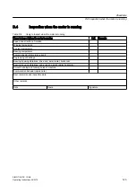
D.3

Inspection at standstill

Table D-3

Items to inspect when machine is at standstill

Items to inspect when machine is at standstill

O.K.

Remarks

Commutator temperature measurement immediately after inspection opening has 

been opened


Check on status of commutator, brush contact surface, oxide film formation


Check on air gap between support and commutator


Check on status of carbon brushes


Brush holder correctly aligned and fastened


Easy movement of brush pressure fingers


Check on length of carbon brushes


Check on easy movement of carbon in the support pockets


Alignment of machine


Electrical and mechanical connections securely tightened


If present, bearing insulation OK


Measurement of isolation resistance of field winding


Measurement of isolation resistance of armature circuit


Clean coal dust from machine


Cleaning the cooling passages


If heat exchanger is installed: filter change or filter cleaning


Check bearing seals


Operating hours 


Sealing of machine


If heat exchanger is installed: Check heat exchanger seals


Next recommended inspection date:
 
Other remarks:
 
Date

Name 

Signature

Checklists
D.3 Inspection at standstill

SIMOTICS DC  1GH5

122

Operating Instructions 02/2016

Summary of Contents for SIMOTICS DC 1GH5

Page 1: ...Answers for industry SIMOTICS DC DC motor Type 1GH5 Operating Instructions Installation Instructions Edition 02 2016 ...

Page 2: ...08 02 2016 10 31 V4 00 ...

Page 3: ...s Edition 02 2016 Introduction 1 Safety notes 2 Description 3 Preparations for use 4 Assembling 5 Electrical connection 6 Commissioning 7 Operation 8 Maintenance 9 Spare Parts 10 Disposal 11 Service and Support A Technical data and drawings B Quality documents C Checklists D ...

Page 4: ...hose who based on their training and experience are capable of identifying risks and avoiding potential hazards when working with these products systems Proper use of Siemens products Note the following WARNING Siemens products may only be used for the applications described in the catalog and in the relevant technical documentation If products and components from other manufacturers are used thes...

Page 5: ...ing the operating mode 23 4 3 Noise emissions 23 4 4 Ensuring cooling 24 4 5 System inherent frequencies 24 4 6 Torsional loading of the drive train due to faults in the electrical supply 24 4 7 Transport and storage 25 4 7 1 Transport markings 25 4 7 2 Checking the delivery 25 4 7 3 Attaching the rotor shipping brace prior to storage 25 4 7 4 Checking the load handling attachments 26 4 7 5 Requir...

Page 6: ...to the driven machine and attaching it to it flange mounting vertical 47 5 3 6 Aligning the machine to the driven machine and mounting flange horizontal IM B5 47 5 3 7 Mounting the machine 48 5 3 8 Axial and radial forces 48 6 Electrical connection 51 6 1 Selecting cables 51 6 2 Bringing in and routing the cables 51 6 3 Terminal designations 52 6 4 Connecting cables 52 6 5 Connecting the main circ...

Page 7: ...al inspection 78 9 1 2 MTTR 80 9 1 3 Main inspection 80 9 1 4 Regreasing rolling contact bearings 81 9 1 5 Regreasing intervals and grease types 82 9 1 6 Clean the machine 83 9 1 7 Checking the carbon brushes 83 9 1 8 Replacing the carbon brushes 84 9 1 9 Setting the brush rocker and brush holder 85 9 1 10 Maintaining the commutator 85 9 1 11 Maintaining terminal boxes 87 9 1 12 Touch up any damag...

Page 8: ... construction type IM B5 109 11 Disposal 111 11 1 Introduction 111 11 2 RoHS restricting the use of certain hazardous substances 111 11 3 Country specific legislation 111 11 4 Dismantling the machine 111 11 5 Disposal of components 112 A Service and Support 113 B Technical data and drawings 115 B 1 Tightening torques for screw and bolt connections 115 C Quality documents 117 D Checklists 119 D 1 S...

Page 9: ...eights 500 to 630 101 Table 10 2 Spare parts rolling contact bearing for 1G 5 1H 5 shaft heights 500 to 630 102 Table 10 3 Spare parts rolling contact bearing for 1G 5 1H 5 shaft heights 500 to 630 103 Table 10 4 Spare parts main terminal box 1XB7710 104 Table 10 5 Spare parts main terminal box 1XB7942 105 Table 10 6 Spare parts auxiliary terminal box 106 Table 10 7 Spare parts speed sensor with c...

Page 10: ...Speed encoder mounting 97 Image 10 1 Stator and rotor 1G 5 1H 5 shaft heights 500 to 630 101 Image 10 2 Rolling contact bearing for 1G 5 1H 5 shaft heights 500 to 630 102 Image 10 3 Rolling contact bearing for 1G 5 1H 5 shaft heights 500 to 630 103 Image 10 4 Main terminal box 1XB7710 104 Image 10 5 Main terminal box 1XB7942 105 Image 10 6 Auxiliary terminal box 106 Image 10 7 Speed sensor with co...

Page 11: ... Text format features The warning notice system is explained on the rear of the inside front Always follow the safety instructions and notices in these instructions In addition to the safety related warning notices which you must read you will find the text in these instructions is formatted in the following way 1 Handling instructions are always formatted as a numbered list Always perform the ste...

Page 12: ...Introduction 1 1 About these instructions SIMOTICS DC 1GH5 12 Operating Instructions 02 2016 ...

Page 13: ...e taken into account at all times The specific setup and safety regulations as well as regulations on the use of personal protective equipment are observed Note Use the services and support provided by the appropriate Service Center Page 113 for planning installation commissioning and servicing work You will find safety instructions in the individual sections of this document Follow the safety ins...

Page 14: ... principle the use of caution is necessary when you are near the machine Always pay attention to your safety Also observe the following to prevent accidents General safety regulations applicable in the country where the machine is deployed Manufacturer specific and application specific regulations Special agreements made with the operator Separate safety instructions supplied with the machine Safe...

Page 15: ...ructions Operate the machine properly CAUTION Hazardous substances Chemical substances required for the setup operation and maintenance of machines can present a health risk Poisoning skin damage cauterization of the respiratory tract and other health damage may result Read the information in these operating instructions and the product information supplied by the manufacturer Observe the relevant...

Page 16: ...inst damage follow the instructions given below Only touch electronic modules if you absolutely have to work on them The body of the person concerned must have been electrostatically discharged and grounded immediately before any electronic modules are touched Electronic modules should not be brought into contact with electrically insulating materials such as Plastic film Plastic parts Insulating ...

Page 17: ...immunity The machine fulfills the requirements regarding interference immunity in conformity with IEC EN 61000 6 2 On machines with integrated sensors e g PTC thermistors the manufacturer of the overall system must himself ensure sufficient interference immunity by selecting suitable sensor signal leads and evaluation units 2 8 Influence on the line power supply through a strongly irregular torque...

Page 18: ...ay be lost on magnetic or electronic data carriers It is forbidden for people with pacemakers to enter the vicinity of the machine Protect the personnel working in the plant by taking appropriate measures such as erecting identifying markings safety barriers and warning signs and giving safety talks Observe the nationally applicable health and safety regulations Do not carry any magnetic or electr...

Page 19: ...zardous areas An explosion can occur if the machine is operated in these areas This can result in death serious injury or material damage Never operate this machine in hazardous areas Schematic diagram Image 3 1 Block diagram of motor type 1GH Cooling The forced ventilated machine is open circuit ventilated with cooling method IC 17 with pipe connections on both sides with cooling method IC 37 The...

Page 20: ...s degree of protection IP54 Ambient conditions Unless otherwise specified the rated powers apply for continuous operation at a coolant temperature of 40 C and an installation altitude of up to 1000 m above sea level Please note any data to the contrary on the rating plate Operating conditions must comply with the specifications on the rating plate Machine design You will find regulations and stand...

Page 21: ...a on the rating plate and the contractual agreements define the limits of proper usage 1 2 3 4 5 6 7 8 9 10 11 12 13 14 15 16 Image 3 2 Schematic rating plate Table 3 3 Data on the rating plate Item Description Item Description Type Supply connection data Serial number Degree of protection Temperature class Construction type Armature voltage V Standards and regulations Armature current A Motor wei...

Page 22: ...ing requirements If a separate wiring space is prescribed for specific auxiliary circuits an additional auxiliary terminal box is mounted on the side of the terminal box Rolling contact bearing The rolling contact bearing is normally a floating bearing at the drive end and a locating bearing at the non drive end You will find further information in section Spare parts Page 99 On machines with a re...

Page 23: ...bed in the chapter titled Safety information Page 13 and in related sections Take appropriate safety precautions covers barriers markings etc to ensure the machine is operated safely within your plant 4 2 Observing the operating mode Observe the machine s operating mode Use a suitable control system to prevent overspeeds thus protecting the machine from damage 4 3 Noise emissions WARNING Noise emi...

Page 24: ...permissible vibration levels being exceeded Excessive vibrations can damage the machine set The vibration limit values according to DIN ISO 10816 3 must not be exceeded 4 6 Torsional loading of the drive train due to faults in the electrical supply In the event of faults in the electrical supply such as failure of the field supply or short circuit across terminals excessive air gap torques can occ...

Page 25: ...be accepted if they are submitted at a later date Report any apparent transport damage to the delivery agent immediately Immediately report any apparent defects missing components to your contact partner These Operating Instructions are part of the scope of delivery keep them in a location where they can be easily accessed 4 7 3 Attaching the rotor shipping brace prior to storage NOTICE Bearing da...

Page 26: ...t correctly secured the machine may be dropped during lifting This can result in death serious injury or material damage Inspect the load handling attachments and lifting gear before use 4 7 5 Requirements for safe lifting and transporting To safely lift and transport the machine the following requirements must be met Personnel operating cranes and fork lift trucks must be appropriately qualified ...

Page 27: ...tion Use suitable rope guiding or spreading devices The weight of the machine is shown on the rating plate WARNING The machine can fall over shift or fall down during transport if the center of gravity is not symmetrical If the center of gravity of a load is not located centrally between the attachment points the motor can tip over or slip out of the lifting equipment and fall when it is being tra...

Page 28: ...ifting and transporting the machine NOTICE Transport damage if the rotor shipping brace is not used The motor can be damaged if it is jolted during transport This can result in material damage Always transport the motor with the rotor shipping brace supplied The rotor shipping brace must be securely attached during transportation Do not remove the rotor shipping brace until you are ready to push o...

Page 29: ...n motors must always be transported in the vertical position if the rotor is not fixed If transport in a horizontal position should prove to be necessary in special cases then fix the rotor before bringing the motor the horizontal position If necessary vertical motors with suitable bearings are supplied by the manufacturing plant in the horizontal position Note Place the machine in a secure and ra...

Page 30: ...at is above flood level and free of vibration veff 0 2 mm s The place of storage must be well ventilated as well as free of dust and frost Provide protection against extreme weather conditions Ensure that the temperature remains stable in the range from 10 C 50 F to 50 C 120 F The room temperature should be approx 10 K above the outside temperature The temperature should not fall below 20 C The re...

Page 31: ...led Do not remove the rotor shipping brace device supplied Open the pressure fingers of the brush holders Take the brushes out of the holders If necessary reapply the anti corrosion protection at the shaft extension Long term storage If you are storing a machine for more than six months you must check its condition every six months Store the machine in accordance with the specifications in Section...

Page 32: ...rotection 5 Reattach the rotor shipping brace if present 6 Pack the machine again 4 7 9 Protection against corrosion If the machine is stored in dry conditions then apply the subsequently listed anti corrosion measures Storage up to six months Apply a coat of corrosion protective compound to all accessible bare metal parts such as the exposed shaft extension flange or machine feet Storage for long...

Page 33: ...esistance lies below the specified value take appropriate remedial measures These remedial measures may necessitate the machine being removed again and transported NOTICE High temperatures The motor components get very hot during operation High temperatures can damage mounting parts such as the cable insulation Temperature sensitive parts such as normal cables or electronic components must not res...

Page 34: ...here Testing the insulation resistance and polarization index Page 34 5 1 3 Testing the insulation resistance and polarization index WARNING Hazardous voltage at the terminals During and immediately after measuring the insulation resistance or the polarization index PI of the stator winding hazardous voltages may be present at some of the terminals Contact with these can result in death serious in...

Page 35: ...ax 10000 Urated rated voltage see the rating plate Umeas DC measuring voltage RC minimum insulation resistance at reference temperature of 40 C Conversion to the reference temperature When measuring with winding temperatures other than 40 C convert the measuring value to the reference temperature of 40 C according to the following equations from IEEE 43 2000 1 RC KT RT RC Insulation resistance con...

Page 36: ... above table Measuring the polarization index 1 To determine the polarization index measure the insulation resistances after one minute and ten minutes 2 Express the measured values as a ratio PI Rinsul 10 min Rinsul 1 min Many measuring devices display these values automatically following the measurement For insulation resistances 5000 MΩ the measurement of the PI is no longer meaningful and cons...

Page 37: ...d to the wall by their mounting feet because of their type of construction must be supported from below by a wall strip for example or bolted 5 2 Lift the machine to where it will be installed and position it 5 2 1 Preconditions for correct alignment and secure attachment Detailed specialist knowledge of the following measures is required in order to correctly align and securely fit the equipment ...

Page 38: ...oad handling attachments and lifting gear before use 5 2 3 Removing the rotor shipping brace If a rotor shipping brace is attached to the machine remove it at the last possible moment for example when you are ready to push on the output or drive element Note Store the rotor locking device Be sure to store the rotor locking device It must be remounted for possible disassembly and transport NOTICE D...

Page 39: ...Paintwork damage If painted surfaces come into contact with the detergent or solvent the paintwork can be damaged Use a suitable solvent to soften thick layers of anti corrosion agent Then push the softened layers off using a piece of hardwood approximately 10 x 10 x 1 cm Do not sand the protective coating down or scrape it off NOTICE Damage to the machine surface If you use metal objects such as ...

Page 40: ...sion element correctly matches the type of balance of the rotor Use only ready drilled and balanced transmission elements Check the hole diameters and the balancing status before pulling them on Thoroughly clean the shaft extension Pulling on Warm up the transmission elements to expand them before pulling them on Select the temperature difference for the heating process to suit the coupling diamet...

Page 41: ...utput element on one shaft extension the feather key can fall out during operation Death or serious injury can result Do not operate the machine unless the transmission elements have been pulled on On shaft extensions without output element make sure that the feather key cannot fall out and shorten it by approximately half for balance type H 5 2 6 Lifting and transporting the machine To safely lif...

Page 42: ... lifted This can result in death serious injury or material damage Comply with the handling instructions on the machine when transporting it Be aware of the possibility of different loads on the sling ropes or lifting straps and the carrying capacity of the lifting equipment Always take account of the center of gravity when transporting or lifting the motor If the center of gravity is not located ...

Page 43: ...otection Water drain holes open IP54 IP55 degree of protection Water drain holes sealed with plastic plugs Where drain holes in the foot area are sealed it can be useful to remove the appropriate screws or plugs depending on the ambient and operational conditions Note Degree of protection for motors with IP54 and better Removing the plastic plug or the plug screw from motors with IP54 or better no...

Page 44: ...n the screwed connections to the specified tightening torques WARNING Incorrect alignment If the machine has not been properly aligned this will mean the fastening parts are subjected to stress distortion Screws may become loose or break the machine will move machine parts could be flung out of place This can result in death serious injury or material damage Carefully align the machine to the driv...

Page 45: ...chines with coupling output to the driven machine in such a manner that the center lines of the shafts at the operating temperature do not have any parallel or angular offset This ensures that no additional forces affect their bearings during operation If the thermal change of the motor and the driven machine is different couple in the cold state with an appropriate alignment offset The alignment ...

Page 46: ... diagram Aligning the machine to the driven machine Table 5 2 Permissible deviations for aligning the machine with flexible coupling Max speed nmax Max parallel offset x Max angular offset y nmax 1500 rpm xmax 0 08 mm ymax 0 08 mm 100 mm D 1500 rpm nmax 3600 rpm xmax 0 05 mm ymax 0 05 mm 100 mm D Note Machine expansion When performing alignment make allowance for the thermal expansion of the machi...

Page 47: ...oning aids 3 Lower the machine slowly toward the driven machine and into the centering so that the flanges do not quite touch Lowering too quickly risks damaging the centering 4 If necessary rotate the machine into the right position so that the clearance holes in the flange are central to the tapped holes 5 Lower the machine completely onto the mating flange so that it is fully in contact then re...

Page 48: ... using the flange fixing bolts finishing by replacing the studs See also Technical data and drawings Page 115 5 3 7 Mounting the machine Secure mounting of different motor variants For secure motor mounting use fastening screws with the required property class per ISO 898 1 e g 10 9 On motors with an upwardly oriented shaft extension make sure that no water enters the top bearing Machines that are...

Page 49: ... are adhered to in accordance with the catalog data or configuration data Use tensioning rails to set up belt driven motors to adjust the belt to the correct tension CAUTION Excessive belt tension On machines with a belt pulley the bearings and shaft can be damaged if the belt tension is too high It is essential therefore that the radial and axial shaft load values are within tolerance Assembling ...

Page 50: ...Assembling 5 3 Installing the machine SIMOTICS DC 1GH5 50 Operating Instructions 02 2016 ...

Page 51: ...e specific cabling requirements 2 Only use guide elements that meet the following requirements Guide elements must be adapted to suit the type and diameter of the cables Guide elements must guarantee IP55 degree of protection The same applies to insertion points where sealing rings and adhesive should be used Guide elements must be appropriate to cable installation conditions For example use cable...

Page 52: ...epending on construction type are provided for connecting the excitation circuit Terminal boxes can also be rotated by 90 in each case depending on the connecting direction Please ensure that winding feeder cables are relaid correctly In this case the insulator plate does not need to be repositioned Under difficult conditions e g with large cross sections or a large number of cables repositioning ...

Page 53: ...hat minimum air clearances as specified in the table above are maintained Connecting using cable lugs 1 Select the cable lugs corresponding to the required cable cross section and the specified dimensions of the terminal connection 2 Tighten the contact and fastening nuts to the torque specified in the table below Table 6 2 Terminal box connection data Terminals 1XB7 gk 602 gk 604 gk 702 gk 704 Ma...

Page 54: ...sion protected hexagon head bolts with at least property class 5 6 per DIN 43673 with hexagonal nuts and spring lock elements e g spring washers per DIN 128 Connection without cable lugs If terminal box size gk 602 or gk 702 is mounted on the machine you can also connect the cables without cable lugs Image 6 3 Connection without cable lugs Electrical connection 6 5 Connecting the main circuit SIMO...

Page 55: ... an adequately sized parallel protective conductor and connect this to the ground terminal on the motor housing Use only the screws supplied Connecting the grounding conductor A hexagon head bolt with a spring lock washer and plain washer or a ground terminal is provided at the designated grounding conductor connection points The hexagon bolt can be used for connecting stranded conductors with cab...

Page 56: ...sure that the following conditions are fulfilled Use only original gaskets The contact points underneath the bolt heads or spring lock washers must be bare metal and protected against corrosion The standard cover fixing screws are an adequate equipotential bonding connection between the terminal box cover and terminal box housing WARNING Electric shock If the equipotential bonding connection fails...

Page 57: ... good time The electrical connection requirements are shown on the terminal diagram pasted into the terminal box Speed sensor Electrically connect a built on speed sensor in situ Temperature monitoring Avoid hazards due to unexpected automatic restarting of the installation after the temperature protection has tripped Implement this in the temperature evaluation and control WARNING Automatic resta...

Page 58: ...ox cover The electrical connections in the terminal box are tight and fully comply with the specifications in the preceding chapters The inside of the terminal box is clean and free of any cable debris All of the clamping bolts and entry parts are securely tightened This also applies to unused terminals Minimum air clearances have been respected The connecting cables are arranged so that they do n...

Page 59: ...unted correctly to ensure effective cooling of the motor The rotor is fully able to turn and does not contact other parts at any point during rotation All electrical and mechanical connections are secure The function is assured Any supplementary motor monitoring devices have been correctly connected Appropriately configured control and speed monitoring functions ensure that the motor cannot exceed...

Page 60: ...stance and polarization index PI provides information on the condition of the machine It is therefore important to check the insulation resistance and the polarization index at the following times Before starting up a machine for the first time After an extended period in storage or downtime Within the scope of maintenance work The following information is provided regarding the state of the windi...

Page 61: ... machine has been in storage for more than four years If the machine has not been stored in accordance with the specifications in the Storage section Procedure 1 Remove the bearing regreasing pipes grease nipples and the bearing cap 2 Flush out the old grease 3 Check the bearings before regreasing If necessary install new bearings 4 Lubricate the bearings and reinstall the bearing components See a...

Page 62: ...the motor is coasting down check the mechanical operation for noise and vibration at the bearings and bearing shields Where the motor is running without any mechanical problems switch it back on again Continue to the maximum speed allowed according to the rating plate In case of uneven running or abnormal noise switch off the machine Determine the cause as it coasts If the mechanical operation imp...

Page 63: ...eady state See also Switching on Page 120 7 6 Overspeed DANGER Overspeed When the exciter circuit is deactivated the machine can enter operating conditions that destroy the machine Death serious injury or material damage will result Interlock the control in such a way that the armature circuit can be connected only when the exciter circuit is energized If the exciter circuit fails switch off the a...

Page 64: ...h off the coolant supply Follow the operating instructions provided by the manufacturer 4 Switch on the anti condensation heating Commissioning 7 7 Switch off SIMOTICS DC 1GH5 64 Operating Instructions 02 2016 ...

Page 65: ...r degree of protection or are required for ensuring proper air flows and hence effective cooling must not be opened during operation WARNING Fire hazard resulting from hot surfaces Certain parts of the machine become hot during operation Severe burns can result from contact with these parts Check the temperature of parts before touching them If required apply suitable protective measures Allow the...

Page 66: ...al damage will result Interlock the control in such a way that the armature circuit can be connected only when the exciter circuit is energized If the exciter circuit fails switch off the armature circuit immediately 8 1 Switching on the machine Procedure 1 Run the machine without a load and check that it is running smoothly 2 If it runs perfectly connect a load 3 If it is possible using the avail...

Page 67: ...arings Refer to the regreasing instructions for the roller bearings on the lubricant plate 8 3 Deactivating If not controlled automatically switch on the anti condensation heating if installed This prevents damage to the winding insulation If not controlled automatically switch any external fans and fans off 8 4 Switching on again after an emergency switching off Check the machine before recommiss...

Page 68: ... external factors Where cylindrical roller bearings are used bearing damage can be caused by external vibration Consult the manufacturer for details of suitable corrective action NOTICE Damage due to improper storage Damage may occur to the motor if it is not stored properly If the machine is to be taken out of operation for more than 12 months suitable anti corrosion preservation packaging and dr...

Page 69: ...59 8 5 3 Measurement of the insulation resistance after an extended stoppage Measuring the insulation resistance and polarization index PI provides information on the condition of the machine It is therefore important to check the insulation resistance and the polarization index at the following times Before starting up a machine for the first time After an extended period in storage or downtime W...

Page 70: ...isted in the Commissioning section See also Commissioning Page 59 8 8 Special operating conditions Operating under light load conditions If a machine is operated continuously or over a long period under light load conditions with approximately half rated current or less damage will occur High brush wear or problems with the commutator may result More details are available in the chapter titled Fau...

Page 71: ... short circuit are faults that overload the machine electrically or mechanically Immediately perform an inspection after such faults Correct the cause of the fault as described in the respective remedial measures section Repair any damage to the machine Operation 8 9 Faults SIMOTICS DC 1GH5 Operating Instructions 02 2016 71 ...

Page 72: ...vibration Operating mode or operating error X Continuous light load duty partial load Change number of brushes and or material X Temporary overload Correct current limit on converter X Continuous overload Correct current limit on converter reduce down periods of rest Cooling fault X Cooling air flow rate too low commutator temper ature too high Improve ventilation circuit Component defect X Intert...

Page 73: ...emperature Use a suitable high temperature grease X X Insufficient lubrication Grease the bearings as instructed X X Bearing canted Properly install the bearing X X Insufficient bearing play Only after consultation with the manufacturer Fit a bearing with greater play X Excessive bearing play Only after consultation with the manufacturer Fit a bearing with lower play X X Bearing corroded Replace t...

Page 74: ...s Improve installation conditions Cooling fault X X X Cooling air too dry Change brush material X X Silicone in the cooling air Remove silicone clean machine and mounting parts X Cooling air contains too much dust Change air ducting use an air filter X Cooling air flow rate too low commutator tempera ture too high Improve cooling Brush fault X X Incorrect or unsuitable brush material Change brush ...

Page 75: ... Correct current limit shorten stand still time Cooling fault X Cooling air too damp Change air ducting X X Cooling air chemically aggressive Change air ducting X Cooling air contains too much dust Change air ducting use an air filter X Cooling air flow rate too high commutator tem perature too low Restrict air ducting if necessary change brush material Brush fault X Incorrect or unsuitable brush ...

Page 76: ...Operation 8 9 Faults SIMOTICS DC 1GH5 76 Operating Instructions 02 2016 ...

Page 77: ...vice Center Page 113 if you require support with servicing maintenance or repair 9 1 Inspection and maintenance WARNING Rotating and live parts Electric machines contain live and rotating parts Fatal or serious injuries and substantial material damage can occur if maintenance work is performed on the machine when it is not stopped or not de energized Perform maintenance work on the machine only wh...

Page 78: ... etc can be left by accident inside the machine after maintenance is performed These can cause short circuits reduce the performance of the cooling system or increase noise in operation They can also damage the machine When carrying out maintenance work make sure that no foreign bodies are left in or on the machine Securely attach all loose parts again once you have completed the maintenance proce...

Page 79: ...ave not deteriorated No impermissible brush sparking occurs in operation Checking during idle time Once the machine has been shut down check that The motor foundation has no indentations or cracks The carbon brushes and commutators are in perfect condition Commutator surfaces have an even finish The brush holders are correctly aligned and mounted Carbon brushes can move freely in the brush guides ...

Page 80: ... be carried out after approximately 16000 operating hours but no later than after two years of operation DANGER Rotating or live parts Rotating or live parts are dangerous Death serious injury or material damage can result if the required covers are removed If no inspection windows are fitted and as a result the appropriate covers need to be removed to allow inspection of the commutating performan...

Page 81: ...during checking should be fully corrected Note The inspection measures listed may be required depending on the plant specification and prevailing operating conditions 9 1 4 Regreasing rolling contact bearings 1 Clean the grease nipple 2 Press in the type and quantity of grease specified on the lubricant plate in portions The shaft must rotate so that the new grease is distributed throughout the be...

Page 82: ...es have lithium soap as the thickening agent and mineral oil as the base oil They exceed the normal requirements of DIN 51825 If you use other K3K or K3N greases some of which only meet the minimum requirements per DIN 51825 halve the regreasing intervals K3N greases have higher temperature reserves than K3K greases NOTICE Damage from mixing lubrication types If greases and oils with different soa...

Page 83: ...rush height monitoring Replace the dirty filter mats Alternatively remove the filter mat and wash it Reinstall the filter mat unwetted after drying Note Damage on the surface of the sound absorber elements On external fans with sound absorbers the surface of the absorber elements is pressure sensitive Air pressure cleaning can damage this surface Air pressure cleaning equipment should not be used ...

Page 84: ...or injuries When working on a brush holder make sure that the holder finger does not snap shut Mounting new carbon brushes 1 When you replace carbon brushes make sure that you replace them with exactly the same type and model You will find the brush type and manufacturer s mark on the upper part of carbon brushes 2 Prepare a strip of emery cloth that is not too coarse The following dimensions are ...

Page 85: ...the brush rocker fixed part 1 brush rocker 2 Adjusting the brush holders 1 Check the radial clearance between the commutator and the lower edge of the brush holder The setting clearance is steplessly adjustable and between 1 5 and 2 mm The brush holder can be set inside the machine 9 1 10 Maintaining the commutator Cleaning the commutator To remove oil grease and or dust clean the commutator with ...

Page 86: ...motor can cause winding damage Suck or blow the dust out Remove the grinding dust with dry oil free compressed air Deburr the edges of the segments if necessary Where the commutator is severely out of round remove the rotor and skim the commutator on a turning machine You can skim the commutator down to the smallest permissible diameter dmin given in the following table Table 9 3 Commutator overha...

Page 87: ...lest permissible commutator diameter Image 9 3 Final work on the commutator after skimming Final measures After the commutator has been reworked adjust the brush rocker and the brush holder Page 85 9 1 11 Maintaining terminal boxes Requirement The machine is de energized Checking for tightness Terminal boxes must be regularly checked for tightness undamaged insulation and tight terminal connection...

Page 88: ...nts 9 1 12 Touch up any damaged paintwork If the paint is damaged it must be repaired in order to protect the unit against corrosion Note Paint system Contact the Service Center Page 113 before you repair any paint damage They will provide you with more information about the correct paint system and methods of repairing paint damage 9 2 Repair When carrying out any work on the machine observe the ...

Page 89: ...loading WARNING Rotor can fall down Eyebolts in accordance with DIN 580 are unsuitable for suspending the rotor The rotor can fall off This can result in death serious injury or material damage Use lifting gear which is suitable for the rotor weight and direction of loading WARNING Machine damage caused by improper repair work Improper servicing work can damage the machine This can cause damages a...

Page 90: ...y a small number of thread grooves are used Depending on the weight of the rotor and the direction of the load other suitable elements with a length of engagement 0 8 x thread diameter should be used Disassembling the machine 1 The drawings and parts lists do not contain any detailed information about the type and dimensions of fixing elements Therefore make sure their assignment is correct before...

Page 91: ... not become damaged Sealing the motor Clean bare joints between parts e g between enclosures end shields and the active parts of bearings Grease the uncoated joints For more stringent degree of protection requirements a joint sealant is often used In this case also seal the joints with a suitable silicone free non setting sealing compound during assembly Use the sealing compound when inserting the...

Page 92: ...viscous oil at approximately 100 C such as DIN 51517 C100 lubricating oil They must be dimensioned such that the shaft can move freely but is tightly enclosed by the rings When installing external V rings the V ring has reached the correct axial position when the end face of the bearing cover is flush with the outer edge of the V ring Use an appropriate auxiliary installation disk for this purpose...

Page 93: ...e threaded hole of the hub of the speed sensor rotor thus forcing the rotor off the conical base of the shaft journal 6 The shaft journals or half couplings mounted on or in the machine shaft extension must be dismantled and replaced if they are damaged When replacing damaged parts such as the tolerance ring please ensure they are correctly arranged Use removable LOCTITE and suitable tools to asse...

Page 94: ... Speed sensor for overhung mounting Disassembly With speed sensors for overhung mounting the speed sensor rotor is bolted to the machine shaft journal or inserted cylindrically Note Damage to the speed sensor The speed sensor can be damaged during motor disassembly Remove the speed sensor before disassembling the motor 1 Unscrew the speed sensor stator and move it away axially 2 Remove the speed s...

Page 95: ... 5 Recommended torques for tightening the shaft journal Thread size Torque Nm M16 20 M20 30 M24 40 Assembly Reinstall the disassembled speed sensor and secure it in position The legend numbers in the following illustration are explained in chapter Spare parts Speed sensor Page 107 Image 9 5 Speed sensor assembly Push the cylindrical shaft extension of the speed sensor rotor as far as possible into...

Page 96: ...ng halves axially 2 The shaft journals or half couplings mounted on or in the machine shaft extension must be removed and replaced if they are damaged When replacing damaged parts such as the tolerance ring please ensure they are correctly arranged Use LOCTITE that can be removed and suitable tools to assemble parts 3 Release or tighten the screwed in coupling part at the hexagon socket head screw...

Page 97: ...sembled and tighten with the correct torques Table 9 7 Tightening torques for mounting couplings Thread size Tightening torque Nm M4 1 3 M5 2 6 M6 4 5 1 Check the elastic connecting link coupling star to ensure that it is in a good condition and in the correct mounting position 2 Mount the complete speed encoder Maintenance 9 2 Repair SIMOTICS DC 1GH5 Operating Instructions 02 2016 97 ...

Page 98: ...Maintenance 9 2 Repair SIMOTICS DC 1GH5 98 Operating Instructions 02 2016 ...

Page 99: ...atic diagrams of the basic versions They are used for spare parts definitions The supplied version may differ in details from these representations Carbon brushes The order number for carbon brushes and or the brush designation is specified on the rating plate You will also find the brush type and manufacturer s mark on the upper part of the brush Terminal box If several terminal boxes are mounted...

Page 100: ...g spare parts via the Internet Spare parts can be ordered online from the spare parts service Spares on Web Spares on Web https b2b extern automation siemens com spares_on_web You can use Spares on Web to determine the order numbers for motor spare parts quickly and easily A short description of how to use Spares on Web is available on the Internet Guide for Spares on Web http support automation s...

Page 101: ...d carbon brushes 8 60 Commutator 24 20 Carbon brushes 10 02 Stator frame with main and commutating coil resistors 24 31 Box type brushholder 10 15 Fixing lug for grounding 24 37 Tandem coil spring brush holder 10 60 Louvered cover 24 50 Brush holder 10 74 Cover with seal 24 60 Single acting clamping shoes for brush holder 10 75 Cover with seal 24 65 Fixing lugs for brush spindle 10 84 Cover with s...

Page 102: ...g contact bearing for 1G 5 1H 5 shaft heights 500 to 630 Table 10 2 Spare parts rolling contact bearing for 1G 5 1H 5 shaft heights 500 to 630 No Designation 4 00 Rolling contact bearing bush floating bearing 5 00 End shield drive end Spare Parts 10 5 Rolling contact bearing SIMOTICS DC 1GH5 102 Operating Instructions 02 2016 ...

Page 103: ...ing for 1G 5 1H 5 shaft heights 500 to 630 Table 10 3 Spare parts rolling contact bearing for 1G 5 1H 5 shaft heights 500 to 630 No Designation 3 00 Rolling contact bearing bush locating bearing 6 00 End shield non drive end Spare Parts 10 5 Rolling contact bearing SIMOTICS DC 1GH5 Operating Instructions 02 2016 103 ...

Page 104: ...l box 1XB7710 No Designation 20 20 Housing 20 28 Seal 20 30 Cover 20 38 Seal 20 51 Entry plate 21 43 Post insulator 21 51 Terminal block for auxiliary circuit 21 61 Terminal strip for auxiliary circuit 22 30 Connection busbar for power circuit Spare Parts 10 6 Terminal boxes SIMOTICS DC 1GH5 104 Operating Instructions 02 2016 ...

Page 105: ... 20 16 Seal 20 20 Housing 20 28 Seal 20 30 Cover 20 38 Seal 20 51 Entry plate with seal 21 43 Post insulator 21 51 Terminal block for auxiliary circuit 21 61 Terminal strip for auxiliary circuits 22 30 Connection busbar for power circuit 22 70 Terminal strip for PE conductor Spare Parts 10 6 Terminal boxes SIMOTICS DC 1GH5 Operating Instructions 02 2016 105 ...

Page 106: ... 10 6 Auxiliary terminal box Table 10 6 Spare parts auxiliary terminal box No Designation 20 09 Auxiliary terminal box 20 20 Housing 20 83 Rubber sleeve Spare Parts 10 6 Terminal boxes SIMOTICS DC 1GH5 106 Operating Instructions 02 2016 ...

Page 107: ...sensor with conical hub for shaft heights 180 to 630 No Designation 55 10 Speed sensor 55 10 1 Speed sensor rotor 55 10 5 Fastening screw 55 10 8 Carbon brushes 55 20 Bearing covers for speed sensor mounting 55 30 Threaded shaft journal with taper 55 38 V ring See also Speed sensor with conical hub Page 93 Spare Parts 10 7 Speed sensor SIMOTICS DC 1GH5 Operating Instructions 02 2016 107 ...

Page 108: ...unting for shaft heights 180 to 630 No Designation 55 10 Speed sensor 55 10 1 Speed sensor rotor 55 20 Bearing covers for speed sensor mounting 55 31 Threaded shaft journal with cylindrical hole 55 31 5 Locking screw 55 35 Tolerance ring See also Speed sensor for overhung mounting Page 94 Spare Parts 10 7 Speed sensor SIMOTICS DC 1GH5 108 Operating Instructions 02 2016 ...

Page 109: ...B5 for shaft heights 180 to 630 No Designation 55 10 Speed sensor 55 20 Bearing covers for speed sensor mounting 55 35 Tolerance ring 55 42 1 Coupling halves at speed sensor end for cylindrical speed sensor shaft 55 42 5 Locking screw 55 44 Coupling star See also Speed sensor for construction type IM B5 Page 96 Spare Parts 10 7 Speed sensor SIMOTICS DC 1GH5 Operating Instructions 02 2016 109 ...

Page 110: ...Spare Parts 10 7 Speed sensor SIMOTICS DC 1GH5 110 Operating Instructions 02 2016 ...

Page 111: ... Hazardous Substances we replace substances that are damaging to the environment by those that are not based on state of the art technology In doing so safety in operation and handling will take priority at all times 11 3 Country specific legislation Note Country specific legislation When disposing of the machine or of waste that is created during the individual phases of its life cycle please obs...

Page 112: ...rease Cleaning substances and solvents Paint residues Anti corrosion agent Coolant additives such as inhibitors antifreeze or biocides Dispose of the separated components according to local regulations or via a specialist disposal company The same applies for cloths and cleaning substances which have been used while working on the machine Packaging material If necessary contact a suitable speciali...

Page 113: ... the rating plate Contact person If you wish to request on site service or order spare parts please contact your local office This office will contact the responsible service center on your behalf You can find your contact person in the relevant contact database www siemens com yourcontact www siemens com yourcontact SIOS App You can obtain optimum support everywhere using the SIOS App The SIOS Ap...

Page 114: ...Service and Support SIMOTICS DC 1GH5 114 Operating Instructions 02 2016 ...

Page 115: ...length of less than 25 mm The clamping length is taken as the distance between the head of the bolt and the point at which the bolt is screwed in Tightening torques The bolted connections with metal contact surfaces such as end shields bearing cartridge parts terminal box parts bolted onto the stator frame should be tightened to the following torques depending on the thread size Table B 1 Tighteni...

Page 116: ...num and to bolts with property class 8 8 according to ISO 898 1 Case C Applies to bolts with property class 8 8 or A4 70 according to ISO 898 1 however only to bolts screwed into components made from materials with higher property class e g cast iron steel or cast steel Note Non standard tightening torques Different tightening torques for electrical connections and bolted connections for parts wit...

Page 117: ...ents C You can find the quality documents here https support industry siemens com cs ww de ps 13419 cert https support industry siemens com cs ww en ps 13419 cert SIMOTICS DC 1GH5 Operating Instructions 02 2016 117 ...

Page 118: ...Quality documents SIMOTICS DC 1GH5 118 Operating Instructions 02 2016 ...

Page 119: ...ng out any work on the machine observe the general safety instructions Page 13 and the specifications contained in EN 50110 1 regarding safe operation of electrical equipment SIMOTICS DC 1GH5 Operating Instructions 02 2016 119 ...

Page 120: ...y cooling system switched on Machine monitored for a while in idling operation With satisfactory idling performance load connected to machine Smooth running checked Values for voltage current and output logged As far as possible the corresponding values for the working machine are logged Temperatures of the bearings windings etc monitored and logged until the sys tem reaches a steady state Operati...

Page 121: ...ush levers can move freely The spring pressure on all brush holders is identical All fixing screws connecting elements and electrical connections are securely tight ened The bearings have been relubricated The bearing insulation is not bridged Supplementary equipment such as temperature monitoring system anti conden sation heating etc are connected and fully operational All protection measures hav...

Page 122: ... of carbon brushes Check on easy movement of carbon in the support pockets Alignment of machine Electrical and mechanical connections securely tightened If present bearing insulation OK Measurement of isolation resistance of field winding Measurement of isolation resistance of armature circuit Clean coal dust from machine Cleaning the cooling passages If heat exchanger is installed filter change o...

Page 123: ...rature Average loading armature current Regreasing of bearings Bearing housing vibrations drive end axial radial horizontal Bearing housing vibrations non drive end axial radial horizontal Smooth running and running noise of machine Commutation behavior spark note Next recommended inspection date Other remarks Date Name Signature Checklists D 4 Inspection when the motor is running SIMOTICS DC 1GH5...

Page 124: ...Checklists D 4 Inspection when the motor is running SIMOTICS DC 1GH5 124 Operating Instructions 02 2016 ...

Page 125: ...Carbon brushes 83 Mounting 84 Removal 84 Replacement 84 Spare parts 99 Center of gravity 27 42 Centering flange 47 Check list Commissioning 121 Inspection 122 Switching on 120 Condensate 66 Connecting cables Selection of 51 Connection 52 with cable lugs 53 without cable lugs 54 Converter 60 Cooling 19 Cooling method 19 Correct usage 21 Corrosion protection 32 Removing 39 D Damage during transporta...

Page 126: ...ive 13 M Machine Aligning to the driven machine 45 Assembly 91 Disassembly 90 Mounting 45 setting down 43 Machine design 20 Machine expansion 46 Machine type 99 Main circuit 22 Maintenance Maintenance intervals 77 Maintenance intervals 80 Minimum radial forces 61 More information 113 Mounting 48 Mounting parts 33 Mounting foot hole dimensions 37 N Natural installation frequency 66 Neutral zone 90 ...

Page 127: ...t assembly 24 Spare parts 113 Auxiliary terminal box 106 Main terminal box 104 105 Ordering 100 Rolling contact bearing 102 103 Speed sensor 107 108 109 Stator and rotor 101 Terminal box 99 Spare parts ordering 99 Spares on Web 100 Speed sensor 57 Standard flange 47 Standstill 70 Stator winding Temperature monitoring 57 Stoppages 67 Roller bearings 69 Storage 31 Storage location 31 Surface of the ...

Page 128: ...Index SIMOTICS DC 1GH5 128 Operating Instructions 02 2016 ...

Page 129: ......

Page 130: ...Siemens AG Process Industries and Drives Postfach 48 48 90026 NÜRNBERG GERMANY www siemens com drives ...

Reviews: