background image

Expanding and assigning parameters to the device 


6.4 Drives (HDD/SSD) 


SIMATIC IPC347G 

50


Operating Instructions, 10/2020, A5E50059993-AA 

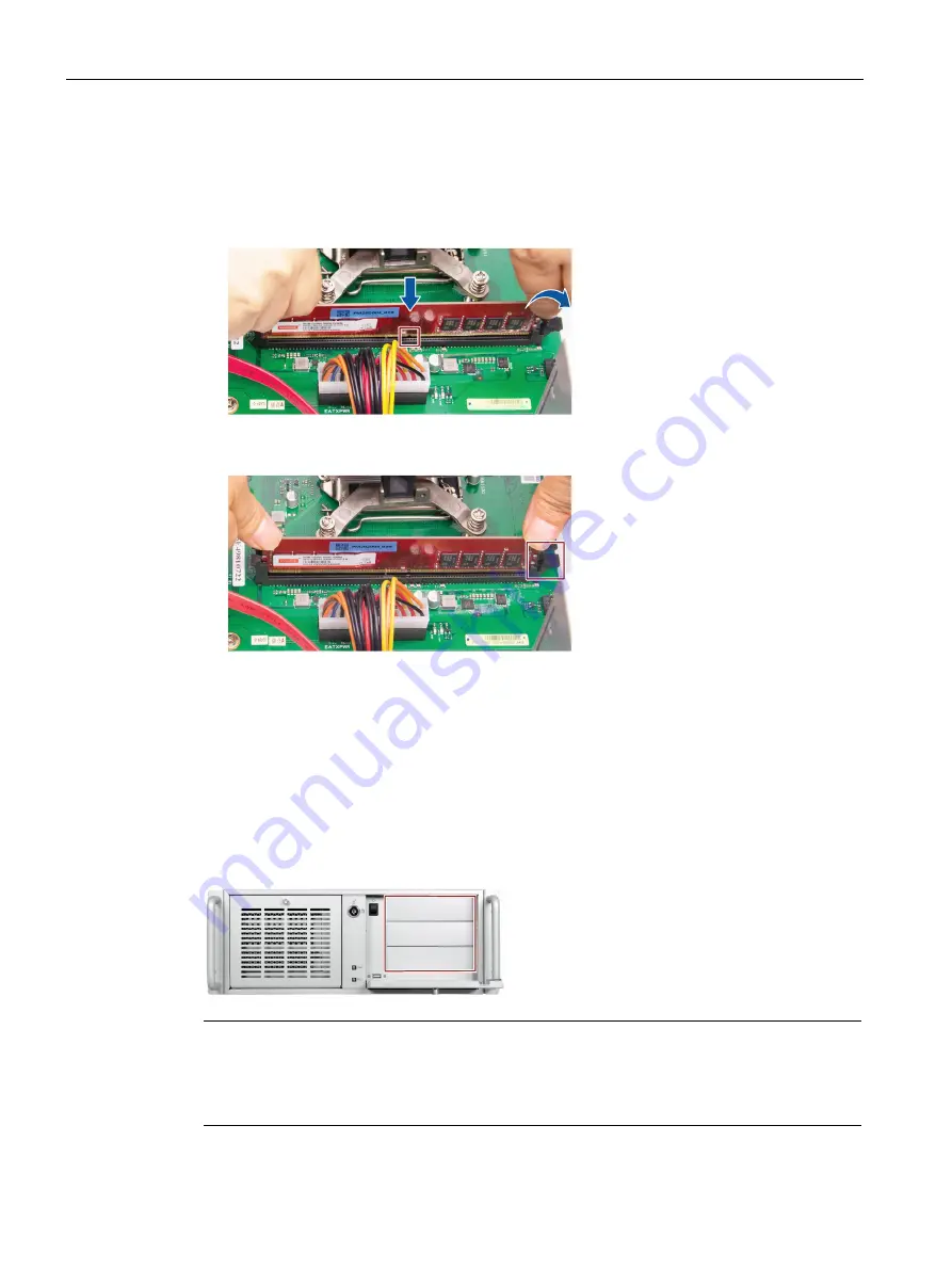
Follow the steps below to install memory module on motherboard memory sockets: 
1.


Press the retaining clips outward to unlock the memory socket.  

2.


Align a memory module on the socket. Note that the notch on the memory must match the 

alignment key on the memory socket. 


3.


Insert and press the memory module into the socket until the retaining clips snap back to 

the original place, and the memory module is seated properly. 


6.4


Drives (HDD/SSD) 

6.4.1


Installation options for drive 

The drive modules are horizontal slot. The SSD and HDDs (with a 5.25” to 2.5” converter) can 

be installed in the slots.  


Note 

If the device is permanently installed, mounted on telescopic rails, it can only be subjected to 

the vibration stresses described below during operation.  
The maximum permitted power loss of the expansion cards is 75 W. 


Summary of Contents for SIMATIC IPC347G

Page 1: ...g and connecting the device 3 Commissioning the device 4 Operating the device 5 Expanding and assigning parameters to the device 6 Device maintenance and repair 7 Technical specifications 8 Dimension drawings 9 Standards and approvals 10 BIOS description 11 Hardware description A Technical support B Markings and symbols C List of abbreviations D ...

Page 2: ...by personnel qualified for the specific task in accordance with the relevant documentation in particular its warning notices and safety instructions Qualified personnel are those who based on their training and experience are capable of identifying risks and avoiding potential hazards when working with these products systems Proper use of Siemens products Note the following WARNING Siemens product...

Page 3: ...personnel Commissioning engineers IT administrators Service and maintenance personnel Basic knowledge required A solid background in electrical installation personal computers Microsoft operating systems and network technology is required to understand this manual General knowledge in the field automation control engineering is recommended Range of validity of these operating instructions These op...

Page 4: ... 6 2 Status display of the Ethernet interface 17 1 5 Internal construction of the device 18 2 Safety instructions 19 2 1 Security information 19 2 2 General safety instructions 19 2 3 Disclaimer for third party software updates 21 2 4 Data protection 21 2 5 Note on transport and storage 22 2 6 Notes on mounting 23 2 7 Notes on ambient and environmental conditions 24 2 8 Information on I O devices ...

Page 5: ...ory modules 48 6 3 1 Usable memory modules 48 6 3 2 Installing memory modules 49 6 4 Drives HDD SSD 50 6 4 1 Installation options for drive 50 6 4 2 Removing the drive module 51 6 4 3 Installing the drive HDD SSD 52 6 4 4 Removing and installing internal HDD SSD 54 7 Device maintenance and repair 55 7 1 Repair information 55 7 2 Maintenance intervals 55 7 3 Removing and installing hardware 56 7 3 ...

Page 6: ...arations 75 8 12 1 Electromagnetic compatibility Industrial and Residential Areas 75 8 12 2 ESD guideline 76 9 Dimension drawings 78 9 1 Dimension drawing of the expansion cards 79 9 2 Dimension drawing of the telescope rails 79 10 Standards and approvals 80 11 BIOS description 83 11 1 BIOS getting started 83 11 2 Main menu 85 11 3 Advanced menu 86 11 4 Hardware Monitor menu 93 11 5 Boot menu 94 1...

Page 7: ... Key slot 112 A 3 10 Intel CPU socket LGA1151 112 A 3 11 DDR4 Memory sockets DIMM_A1 DIMM_B1 113 A 3 12 SATA 6 0 Gbps Port Connectors SATA6G_1 SATA6G_2 SATA6G_3 113 A 3 13 Battery socket 113 B Technical support 114 B 1 Service and support 114 B 2 Troubleshooting 115 B 2 1 Problems with device functions 115 B 2 2 Problems when booting the device 116 B 2 3 Problems when using expansion cards 117 C M...

Page 8: ...ion on Operating Instructions of the device Installation of the device Steps for connecting the device to the power supply Connecting I O devices Switching the device on Supplied in printed form with the device Supplied data storage medium Current product infor mation Current notes on the device Changes compared with these operating instructions Online at SIMATIC IPC Documentation http www siemens...

Page 9: ... of interfaces Lockable front cover Prepared for mounting on telescopic rails Note The supplied device may differ in some details from the figures contained in this manual Within some of the figures one device is used to represent all devices SIMATIC IPC347G configuration plan Type 19 rack 4 U Mounting Support horizontal installation Chipset Intel H110 CPU type Intel Pentium Processor G4400 2C 2T ...

Page 10: ...ATIC IPC offers system integrators cabinet designers system engineers and machine designers a 19 rack PC platform for high performance applications and IT applications on the control and cell level for Process and visualization applications Industrial image processing Quality assurance and monitoring tasks Measurement control and rule based tasks Data acquisition and management The SIMATIC IPC has...

Page 11: ...2020 A5E50059993 AA 11 1 4 External design of the device 1 4 1 Front panel Front left door Front right door Lock Connections for USB 2 0 devices compatible with USB 1 1 On off button HDD status display Connection for USB 2 0 devices compatible with USB 1 1 Power status display Drive bays 3 x 5 25 ...

Page 12: ...ice SIMATIC IPC347G 12 Operating Instructions 10 2020 A5E50059993 AA 1 4 2 Rear of the device Power supply Function earth Air outlet Interfaces Extensible interface Expansion slots for 3 PCI 3 PCIe x4 Gen 2 0 1 PCIe x16 Gen 3 0 Open direct plug sockets ...

Page 13: ...rive bays Mounting location 1 Mounting location for 3 5 or 2 5 drive in a shock proof vibration proof fixture or for 5 25 drive or components Mounting location 2 Mounting location for 3 5 or 2 5 drive in a shock proof vibration proof fixture or for 5 25 drive or components Mounting location 3 Mounting location for 3 5 or 2 5 drive in a shock proof vibration proof fixture or for 5 25 drive or compo...

Page 14: ...Ethernet Port for 10 100 1000Mbps LAN the MAC Address is listed in Component label Line in blue Connection for analog audio source 3 5 mm phono jack Line out green Connection for active speakers or headset 3 5 mm phono jack Microphone pink Connection for microphone 3 5 mm phono jack USB 3 0 2 Connections for USB devices compatible with USB 2 0 1 1 DP port X71 Connection of a digital monitor 3 Keyb...

Page 15: ...ure shows the power supply connector 1 4 5 Operator controls WARNING Risk of electric shock The buttons and switches described in the following do not fully disconnect the device from the line voltage You also need to the notes and information under Switching off the device Page 40 On Off switch The following figure shows the location of the on off switch On Off switch ...

Page 16: ...ant for example after a power failure Take this into account when designing the plant The following figure shows the position of the on off button at the front of the device The on off button has three functions Switch on the PC press the on off button once shortly Shut down the operating system and switch off PC press the on off button once shortly 1 Switch off PC without shutting down the operat...

Page 17: ...provide information on the status of the device components Item Status display Meaning LED Description POWER Operating mode of the PC Off Hibernate switched off or unplugged Green PC in operation HDD Display for hard disk access Off No accessing Green flashing Accessing data 1 4 6 2 Status display of the Ethernet interface The Ethernet interfaces are numbered on the enclosure to identify them clea...

Page 18: ...cal link disconnects Interface disabled Yellow Active connected Yellow flashing Data transfer active LED 2 Data transmission rate OFF 10 Mbps Orange 100 Mbps Green 1000 Mbps 1 5 Internal construction of the device Power supply Heat sink of the processor Motherboard with slots for memory slots Drive cage Motherboard Slots for expansion cards Card holder for expansion cards On the enclosure Numberin...

Page 19: ...priate security measures e g firewalls and or network segmentation are in place For additional information on industrial security measures that may be implemented please visit https www siemens com industrialsecurity Siemens products and solutions undergo continuous development to make them more secure Siemens strongly recommends that product updates are applied as soon as they are available and t...

Page 20: ...disconnect the device from the mains voltage before performing work on the device or when the device will not be used over an extended period of time For control cabinet mounting Use a central easily accessible AC circuit breaker close to the device if possible Risk of lightning strikes DANGER Risk of lightning strikes A lightning flash may enter the mains cables and data transmission cables and j...

Page 21: ... third party software updates This product includes third party software Siemens AG only provides a warranty for updates patches of the third party software if these have been distributed as part of a Siemens software update service contract or officially released by Siemens AG Otherwise updates patches are undertaken at your own risk You can find more information about our Software Update Service...

Page 22: ...d device A damaged device can be under hazardous voltage and trigger a fire in the machine or plant A damaged device has unpredictable properties and states Death or serious injury could occur Avoid installing and commissioning a damaged device Label the damaged device and keep it locked away Send off the device for immediate repair Damage from condensation NOTICE Damage from condensation If the d...

Page 23: ...the air flow required for safe operation of the device is guaranteed Mechanical load When mounting the equipment in the rack ensure that a hazardous condition is not caused due to an uneven mechanical load Circuit overload When connecting the devices to the power supply observe the rated values specified on the nameplate of the devices Reliable grounding Reliable grounding of rack mounted equipmen...

Page 24: ...ms Only operate the device in the ambient conditions specified in the technical specifications Observe the permitted mounting positions of the device Do not obstruct the venting slots of the device When the device is operated in severe environments which are subject to caustic vapors or gases ensure sufficient clean air is provided Clean the enclosure surface with a damp cloth and make sure that n...

Page 25: ... technical specifications High frequency radiation above the specified immunity limits can result in malfunctioning of the device Persons are injured and the plant is damaged Avoid high frequency radiation Remove radiation sources from the environment of the device Switch off radiating devices Reduce the radio output of radiating devices Read the information on electromagnetic compatibility Read t...

Page 26: ...tive 2 9 Notes on device and system extensions Device and system extensions CAUTION Fire hazard due to overheating of the device Expansion cards generate additional heat The device might overheat or cause a fire Observe the safety and installation instructions for the expansion cards Observe the max permissible power consumption values NOTICE Damage caused by device and system extensions Device an...

Page 27: ... of liability All technical specifications and approvals of the device only apply if you use expansion components that have a valid CE approval CE mark Observe the installation instructions for expansion components in the associated documentation UL approval of the device only applies when the UL approved components are used according to their Conditions of Acceptability We are not liable for func...

Page 28: ...or installation in operating systems SIMATIC IPC347G Quick Install Guide SIMATIC IPC347G Operating Instructions Operating instructions for your ordered Microsoft Windows operating system on this device Operating system Depending on the ordered device configuration the device is equipped with or without one of the following installed operating systems You can find information on ordered Microsoft W...

Page 29: ...n charge Have the shipper confirm the transport damage immediately 2 Unpack the device at its installation location 3 Keep the original packaging in case you have to transport the unit again 4 Check the scope of delivery Page 28 for completeness and damage Please inform the delivery service immediately if the package contents are incomplete or damaged or do not correspond with your order 5 Please ...

Page 30: ...ocated on the inside of the front door Identification data Where is it Order number Serial number Product version Unified Siemens address for product liability Ethernet address MAC address COA label The COA label Certificate of Authenticity is located inside the front door Note The COA label is only available for devices delivered with Microsoft Windows operating system installed Example of the CO...

Page 31: ...and spread of fire Install the device only in one of the described permitted mounting positions For installation of control cabinet observe the country specific regulations Provide adequate volume in the switchgear cabinet for air circulation and heat transport Keep at least 10 cm between the device and the switchgear cabinet Do not cover the vent slots of the device Ensure that the maximum air in...

Page 32: ...and 19 rack systems Additional installation information You can also find additional information in the QIG Quick Install Guide which comes with your device 3 2 2 Securing device WARNING Dangerous voltage and fire hazard Improper actions during installation and assembly may lead to personal injury and or substantial damage to equipment You should observe the installation and assembly notes under N...

Page 33: ...e more than 5 mm into the device Use the brackets on the front panel to carry and lift the unit Mounting holes Detailed information on the position of the mounting holes for angle brackets or telescopic rails can be found here Dimension drawing of the telescope rails Page 79 and Technical specifications of the telescopic rails Page 75 The figure below shows the position of the mounting holes for a...

Page 34: ...wer outlet Use a flexible cable with the following features 230 V supply voltage of the USA and Canada Type SJT with three conductors The connector must be compliant with NEMA 5 15 Conductor cross section 18 AWG Cable length 4 5 m 120 V supply voltage of the USA and Canada Type SJT with three conductors The connector must be compliant with NEMA 5 15 Conductor cross section 18 AWG Cable length 4 5 ...

Page 35: ... The connection for the function earth is labeled with the following symbol You can find information on the position of the functional earthing connection under Rear of the device Page 12 Requirement PH2 screwdriver Cable lug for M4 Function earth with minimum cross section of 2 5 mm2 copper cable Procedure 1 Clamp the cable lug on the function earth 2 Firmly attach the cable lug to the function e...

Page 36: ...f electric shock The on off button and on off switch do not fully disconnect the device from the mains There is also a risk of fire if the device or connecting lines are damaged Always fully disconnect the device from the mains voltage before performing work on the device or when the device will not be used over an extended period of time For control cabinet mounting Use a central easily accessibl...

Page 37: ...es Information on the position of the interfaces is available in Interfaces and connections Page 14 2 Secure the cables Page 38 with strain relief if needed Connecting audio devices Depending on the function a UAJ connector has 2 4 contact surfaces Depending on the function or standard the assignment of the contacts varies The audio controller of the device recognizes the assignments of the contac...

Page 38: ...ia Standard Ethernet interfaces RT SIMATIC NET Use this software package to create operate and configure an innovative network for Field Control level Additional information is available under SIMATIC NET https new siemens com global en products automation industrial communication html The software package and the documentation are not included in the scope of delivery Additional information You c...

Page 39: ...is not installed correctly The operating safety of the device and the plant is at risk Do not switch off the device during the entire installation process Do not change the default values in the BIOS setup Requirements Ensure the following preparation work have been done before you start the commissioning Peripheral equipments keyboard mouse and monitor are connected The power supply is connected ...

Page 40: ... lit green The device is switched off but not fully disconnected from the line voltage Fully disconnecting the device from the line voltage WARNING Risk of electric shock The on off button and on off switch do not fully disconnect the device from the mains There is also a risk of fire if the device or connecting lines are damaged Always fully disconnect the device from the mains voltage before per...

Page 41: ...ICE Data loss If a hardware reset is performed the device undergoes a hard reboot Data in the main memory is deleted Data on the data storage media might be lost The device might be damaged Perform a hardware reset only in the case of an emergency Hardware reset with on off button Press the on off button for more than 4 seconds The unit switches off Press the power button again to turn the device ...

Page 42: ...PC347G 42 Operating Instructions 10 2020 A5E50059993 AA Operating the device 5 5 1 Opening the front door Procedure 1 Unlock the front door with the key 2 Open the front right door in the direction of the arrow ...

Page 43: ...the air inlet temperature The onboard hardware monitor automatically detects and displays the air outlet temperature Fan monitoring Monitor the CPU FAN and chassis Fan Check the function in the Hardware Monitor Menu Page 93 of BIOS CPU FAN control Auto Mode CPU Fan speed change based on CPU temperature CHA Fan1 Control Auto Mode Chassis Fan speed change based on mother board tem perature Silent Mo...

Page 44: ...per intervention in the device endangers operational reliability and may damage the device The results are personal injuries and damage to the plant Take the following precautions Always disconnect the power plug before you open the device Close the device after every intervention NOTICE Electrostatic sensitive devices ESD The device contains electronic components that may be destroyed by electros...

Page 45: ...rs to the device 6 1 Open the device SIMATIC IPC347G Operating Instructions 10 2020 A5E50059993 AA 45 Procedure 1 Remove the retaining screws 2 Move the cover in the direction as the arrow 3 Lift the cover from the back and remove it ...

Page 46: ...specified dimensions If the height of the card exceeds the specified dimension you may experience contact problems malfunctions and difficulties with the assembly The permitted expansion card dimensions are specified in the section Dimension drawing of the expansion cards Page 79 The PCI card is limited to 5 V and universal board The total power consumption of the modules is not permitted to excee...

Page 47: ...IPC347G Operating Instructions 10 2020 A5E50059993 AA 47 Procedure 1 Remove the retaining screw and remove the card holder 2 Remove the slot bracket of the slot for the expansion card 3 Insert the expansion card into the slot 4 Secure the expansion card with the designated screw ...

Page 48: ...therboard provides two DDR4 memory sockets and supports dual channel technology The memory capacity of the device can be upgraded to a maximum of 32 GB You can use approximately 3 2 GB of this memory in a 32 bit operating system and much more in a 64 bit operating system The table below shows the supported memory types of motherboard Module type Module Size Description DDR4 SDRAM 4 GB DDR4 2133Mhz...

Page 49: ... easier access to the memory modules see Changing the power supply Page 60 To install the memory module WARNING Only install memory modules designed for the default motherboard Recommend selecting memory modules with the same brand capacity speed and chips if you use multiple Memory Modules Unplug the power cord from the power outlet before installing Memory Module A memory module can be installed...

Page 50: ...ent key on the memory socket 3 Insert and press the memory module into the socket until the retaining clips snap back to the original place and the memory module is seated properly 6 4 Drives HDD SSD 6 4 1 Installation options for drive The drive modules are horizontal slot The SSD and HDDs with a 5 25 to 2 5 converter can be installed in the slots Note If the device is permanently installed mount...

Page 51: ...he mounting locations these may be exposed to the following vibration stresses during operation For HDD 10 to 58 Hz 0 015 mm 58 to 200 Hz 1 96 m s2 For SSD 10 to 58 Hz 0 0375 mm 58 to 200 Hz 4 9 m s2 Vibrations above 500 Hz are not permitted 6 4 2 Removing the drive module Requirement The device is fully disconnected from the line voltage see Switching off the device Page 40 PH2 screwdriver Proced...

Page 52: ...You can find information on the correct mounting location for 5 25 drives in a drive cage under Installation options for drive Page 50 Requirement An original spare part i e an Assembly Kit HDD SDD for 5 25 tray approved for this device The device is fully disconnected from the line voltage see Switching off the device Page 40 The device is open see important information in Open the device Page 44...

Page 53: ...disk in the corresponding slot Note If you want to install a 2 5 hard disk drive or 3 5 hard disk drive you need to install a corresponding converter in addition Recommend installing the hard disk in the middle slot of the drive module 3 Install the driver cage again 4 Connect the power and data cables to the drive 5 Install the drive bay according to the reverse steps of removing the drive bay ...

Page 54: ...disconnected from the line voltage see Switching off the device Page 40 The device is open see important information in Open the device Page 44 The drive bay is taken out of the chassis Procedure Loosen the four screws on the drive bay plate and remove the hard disk from the drive bay Procedure for installing the hard disk drive Place the hard disk onto the drive bay plate and secure the drive wit...

Page 55: ...stall or exchange system expansions and damage your device the warranty becomes void For this reason please observe the information in Notes on device and system extensions Page 26 7 2 Maintenance intervals To maintain high system availability we recommend the preventative replacement of those PC components that are subject to wear The table below indicates the intervals for this replacement Compo...

Page 56: ... fan cover has been removed see Replacing the device fan Page 57 An original spare part for example a filter pad with the same type Procedure Removing the filter 1 Unlock the front cover with the key 2 Pull the handle in the direction of the arrow to open the left front door 3 Unscrew the marked screws 4 Pull the marked screw to open the fan bracket 5 Remove the filter in the direction of the arro...

Page 57: ...ewdriver Procedure Removing the fan 1 Unlock the front cover with the key 2 Pull the handle in the direction of the arrow to open the left front door 3 Unscrew the marked screws 4 Pull the marked screws to open the fan bracket 5 Remove the highlighted screws 6 Remove the fan in the direction of the arrow 7 Pull the fan plug from the connector Procedure Installing the fan To install the fan follow ...

Page 58: ...t sunlight moisture and condensation Prior to replacement WARNING Risk of explosion and release of harmful substances An explosion or fire HAZARD could occur through fitting a battery of the wrong type Improper handling of lithium batteries also can result in an explosion of the batteries Explosion of the batteries and the released pollutants can cause severe physical injury Aged batteries jeopard...

Page 59: ...e du produit contactez le support technique Page 114 Siemens Ne jetez pas au feu des piles au lithium n effectuez pas de soudage sur la pile ne la rechargez pas ne l ouvrez pas ne la court circuitez pas n intervertissez pas les pôles ne la chauffez pas à plus de 100 C et protégez la de l ensoleillement direct de l humidité et de la condensation NOTICE Disposal of batteries Batteries do not belong ...

Page 60: ... from socket 3 Press the new battery into the socket applying slight pressure 4 Close the device 5 Reconfigure the BIOS setup Note The configuration data of the device may be deleted when the battery is replaced Record the current configuration data in the BIOS setup 7 3 4 Changing the power supply Requirement The device is fully disconnected from the line voltage see Switching off the device Page...

Page 61: ...er cables in the enclosure 3 Remove the four fixing screws that are marked in the following figure 4 Pull the power supply upward and out of the housing 5 Install the new power supply 6 Fasten the power supply with the screws shown 7 Connect the cables to the drives and the motherboard 8 Use cable ties to reattach the power supply cables to the enclosure 9 Close the device 10 Check the safe state ...

Page 62: ...n the device Page 44 An original spare part for example a processor with the same type Only an approved processor is permitted to be installed on the motherboard NOTICE Damage to the processor If the processor is operated with a higher clock frequency than permitted it can be destroyed or cause loss of data Operate the processor only at a clock frequency that is equal to or less than the permitted...

Page 63: ...highlighted screws The fourth screw is hidden by the heat sink in the figure 4 Remove the heat sink 5 Unlock the socket and lift the socket cover 6 Remove the processor 7 Install the new processor on the socket as shown in the figure When installing the CPU make sure you aligned the highlighted arrow on the processor with pin 1 in the CPU socket ...

Page 64: ...that is equal to or less than the permitted clock frequency 7 3 6 Replacing the motherboard Requirement The device is fully disconnected from the line voltage see Switching off the device Page 40 The device is open see important information in Open the device Page 44 An original spare part that is a motherboard of the same type The motherboard as spare part is supplied without processor and memory...

Page 65: ...Information on installation of the operating system is available on the Internet Microsoft Windows 10 https support industry siemens com cs ww en view 109749498 Note Before installing Windows 10 set the Boot mode select as UEFI in BIOS On how to set the boot mode refer to Boot menu Page 94 7 4 1 Installing software and drivers Requirements Windows 10 operating system is installed in your IPC You n...

Page 66: ...art the Documentation and Drivers suite from the USB flash drive by executing the START_DocuAndDrivers CMD file 3 Install the desired software and drivers 4 Follow the below steps and click the icon to install the required driver Note For a new installation of Windows operating systems the chipset driver must be installed before all other drivers if required Step 1 install the chipset driver 1 Cli...

Page 67: ...etwork Connections Driver 2 Click to install the LAN driver 3 Click the Install Drivers and Software button in the pop up window 4 Click Yes to confirm the user account control question 5 Click Next to continue 6 Select the radio button before I accept the terms in the license agreement and click Next to accept license agreement 7 Set the setup option as you like and click Next 8 Click Install to ...

Page 68: ...lick OK to restart the computer for the changes to take effect Step 6 install the SIO driver 1 Click Step 6 Nuvoton SIO COMMPort Driver 2 And then click to install the Super IO driver 3 Click Yes to confirm the user account control question 4 Click Yes to continue 5 Click Install to continue the installation 6 Select the radio button next to Yes I want to restart my computer now and click OK to re...

Page 69: ...le number 6AG4012 2 for details refer to the ordering documentation Dimensions 481 176 509 W H D in mm Detailed dimensional specifications can be found in Dimension drawings Page 78 Weight 13 3 up to 17 kg depending on the equipment Power Supply Input Rating 100 VAC to 240 VAC 6 to 3A 60 to 50Hz Rated output power 350W 3 3V 5V 105W Power consumption Full load 100 350 W at 82 efficiency Typical loa...

Page 70: ...er supply 8 3 1 Power requirements of the components maximum values Component Voltage 5 V 3 3 V 12 V1 12 V2 CPU 12 V 5 V aux motherboard with processor and heat sink 2 5 A 1 2 A 4 6 A 0 1 A 0 3 A Front fan 0 5 A Basic system 1 2 5 A 1 2 A 5 1 A 0 1 A 0 5 A Expansions Hard disk drive SATA 1 0 6 A 0 8 A DVD ROM 1 0 9 A 0 8 A DVD writer 1 1 1 A 1 4 A Single lines of current max per mitted 2 25 A 25 A...

Page 71: ...C IEC 61000 6 4 A1 CISPR 22 0 15 to 0 5 MHz 79 dB μV QP 66 dB μV A 0 5 to 30 MHz 73 dB μV QP 60 dB μV A Radiation Emission IEC 61000 6 4 CISPR 22 30 to 230 MHz 40 dB μV m QP 10 m distance 230 to 1000 MHz 47 dB μV m QP 10 m distance 1 to 3 GHz 76 dB μV m P 56 dB μV m A 3 m distance 3 to 6 GHz 80 dB μV m P 60 dB μV m A 3 m distance Harmonic currents EN 61000 3 2 class D Voltage fluctuation and flick...

Page 72: ...g to IEC 60068 2 78 IEC 60068 2 30 Operation 5 up to 80 at 25 C no condensation Gradient 10 K h no condensation Storage transport 5 up to 95 at 25 C no condensation Gradient 20 K h no condensation Atmospheric pressure Operation 1013 up to 795 hPa corresponds to an altitude of 0 m to 2000 m Storage transport 1013 up to 660 hPa Corresponds to an altitude of 0 m to 3500 m Mechanical ambient condition...

Page 73: ... 1151 socket Proces sor support 65W CPU Slots for memory modules 2 x DIMM slots for DDR4 2133 expandable to 32 GB Main memory 4 up to 32 GB DDR4 SDRAM PC4 3200T Max of 2 8 GB can be used for 32 bit versions of operating system and applica tions see order documents for equipment Power consumption per PCIe slot with x4 expansion card maximum permit ted 3 3 V 3 A 12 V 2 1 A 3 3 Vaux 0 4 A Power consu...

Page 74: ...ces Observe the information in Applicability of technical specifications Page 69 and use only original connections of the I O to be connected COM On the rear panel 2 RS232 RS485 RS422 9 pin header On the motherboard 2 RS232 9 pin header DP Connection of a digital monitor 1 DP The maximum length of DP cable is less than 15 meters and the DP cable must comply with VESA DisplayPort standard VGA Conne...

Page 75: ...nguage Multi Language User Interface MUI 6 languages English Chinese German French Spanish Italian You can find information on ordered Microsoft Windows operating systems under Important instructions and manuals for operating the device Page 8 Boot mode and partitions in the delivery state Delivery state for Windows 10 In the delivery state Windows 10 boot in UEFI mode The following table lists th...

Page 76: ...labeled with an appropriate symbol NOTICE Damage to ESD from touch Electrostatic sensitive devices ESD can be destroyed by voltages which are far below the human perception limit If you touch a component or electrical connections of a module without discharging any electrostatic energy these voltages may arise The damage to a module by an overvoltage can often not be immediately detected and only ...

Page 77: ...isconnect the power supply before you install or remove modules which are sensitive to ESD Pay attention to good grounding When handling electrostatical sensitive devices make sure that persons the workstation and devices tools and packaging used are properly grounded This way you avoid static discharge Avoid direct contact As a general rule do not touch electrostatic sensitive devices except in t...

Page 78: ...SIMATIC IPC347G 78 Operating Instructions 10 2020 A5E50059993 AA Dimension drawings 9 Front view and top view All dimensions in mm ...

Page 79: ... Operating Instructions 10 2020 A5E50059993 AA 79 9 1 Dimension drawing of the expansion cards Long PCI card PCIe card 9 2 Dimension drawing of the telescope rails Dimensions for bore holes for telescopic rails Dimensions mm T1 Tolerances of 0 1mm 0 004 T2 Tolerances of 0 3mm 0 01 ...

Page 80: ...rmonisation of the laws of Member States relating to electrical equipment designed for use within certain voltage limits until 19 04 2016 2014 35 EU Directive of the European Parliament and of the Council of 26 February 2014 on the harmonisation of the laws of the Member States relating to the making available on the market of electrical equipment designed for use within certain voltage limits Off...

Page 81: ...wn expense Shielded Cables Shielded cables must be used with this equipment to maintain compliance with FCC regulations Modifications Changes or modifications not expressly approved by the manufacturer could void the user s au thority to operate the equipment Conditions of Opera tions This device complies with Part 15 of the FCC Rules Operation is subject to the following two con ditions 1 this de...

Page 82: ...ements of Korean certification This product satisfies the requirement of the Korean Certification KC Mark 이 기기는 업무용 A 급 전자파 적합기기로서 판매자 또는 사용자는 이 점을 주의하시기 바라며 가정 외의 지역에서 사용하는 것을 목적으로 합니다 BIS This product meets the requirements of India certification BSMI This product meets the requirements of CNS14336 1 099 09 30 CNS13438 095 06 01 generic standard 警告使用者 本產品是甲類的資訊產品 在居家的環境中使用時 可能會造成射頻干擾 在 這類情況下 使用者...

Page 83: ...enter BIOS Setup at startup 1 Power on the device 2 Press DELETE or ESC key on your keyboard during the Power On Self Test POST when the SIEMENS logo is shown on screen The AptioTM TSE main BIOS setup menu is displayed You can access the other setup screens from the main BIOS setup menu such as Advanced menu Note During the startup if DELETE or ESC is not pressed POST continues its routines If the...

Page 84: ... the following main items Main For changing the basic system configuration Advanced For changing the advanced system settings Hardware Monitor For displaying the system temperature power status and changing the fan settings Boot For changing the system boot configuration Security For setting the administrator or user password configure trusted devices or set secure boot Save Exit For selecting the...

Page 85: ...s Enable user to load optimized default values in BIOS Setup Menu F4 Save Exit Enable user to save the current configuration and exit BIOS Setup Menu ESC Right Click Exit The ESC Key or Right Click allows you to discard any change have made and exit BIOS setup menu Configuration fields Configuration fields show the values for the menu items If an item is user configurable you can change the value ...

Page 86: ...e arrow key to select the data 2 Navigate to the month day and year and type in the value as you need Press Enter to jump to next filed 3 Press F4 key and save the change System Time You can follow the steps to set the system time 1 Use arrow key to select the data 2 Navigate to the hour minute and second and type in the value as you need Press Enter to jump to next filed 3 Press F4 key and save t...

Page 87: ... 1 options All 1 2 3 All EIST Enable or disable Enhanced Intel SpeedStep Technology Enabled Disabled Enabled Reserve for OS memory Select the reserve value for operating system memory Dynamic 3 GB Dynamic Chipset Configuration In the Chipset Configuration page you can change the platform settings System parameters Function description Configuration options Default setting Primary Dis play 1 Select...

Page 88: ...EG Enabled Auto CPU Graphics PEG Disa bled Auto CPU Graphics PEG SATA Configuration When you enter the BIOS Setup the BIOS automatically detects the presence of SATA devices If no SATA device is installed to the corresponding SATA port the SATA Port items show Empty System parameters Function description Configuration options Default setting SATA6G_1 Enable or disable the SATA port SATA6G_1 Enable...

Page 89: ...o Enabled ACPI Settings In the ACPI Settings page you can change the ACPI settings System pa rameters Function description Configuration options Default setting Restore AC Power Loss Restore the AC power loss Always On The system goes into on state after an AC power loss Always Off The system goes into off state after an AC power loss Last State The system goes into either off or on state whatev e...

Page 90: ...6 7 9 10 11 12 IO 2F8h IRQ 3 4 5 6 7 9 10 11 12 IO 3E8h IRQ 3 4 5 6 7 9 10 11 12 IO 2E8h IRQ 3 4 5 6 7 9 10 11 12 Auto COM1 Control When you set the Serial Port 1 to Ena bled this item allows you to select the COM1 mode RS232 RS422 RS485 RS232 Serial Port 2 Configuration Serial Port 2 Enable or disable the serial port COM 2 Enabled Disabled Enabled Change Set tings When you set the Serial Port 2 t...

Page 91: ...sabled Enabled Change Set tings When you set the Serial Port 4 to Ena bled and allows you to select the Serial Port base address Auto IO 2E0h IRQ 7 IO 3E8h IRQ 3 4 5 6 7 9 10 11 12 IO 2E8h IRQ 3 4 5 6 7 9 10 11 12 IO 2F0h IRQ 3 4 5 6 7 9 10 11 12 IO 2E0h IRQ 3 4 5 6 7 9 10 11 12 Auto M 2 Detect Information This page displays the information of the connected M 2 devices Onboard Device Configuration...

Page 92: ...nction description Configuration options Default setting Network Stack Enable or disable the UEFI Network Stack Enabled Disabled Enabled Ipv4 PXE Support Enable or disable the Ipv4 PXE Boot support Enabled Disabled Enabled Ipv6 PXE Support Enable or disable the Ipv6 PXE Boot support Enabled Disabled Enabled PCIE Configuration In the PCIE Configuration page you can configure the onboard devices Sys...

Page 93: ...IEX4_3 Gen1 Gen2 Auto Gen1 Gen2 Auto PCIEX4_3 Non Compliance mode Detect Non Compliance PCI Express Device in PCIEX4_3 Enabled Disabled Disabled 11 4 Hardware Monitor menu Hardware Monitor menu The Hardware Monitor menu displays the system temperature power status and allows you to change the fan settings System parameters Function description Configuration op tions Default setting CPU Temper atur...

Page 94: ... Mode Disabled Mode Silent Mode CHA Fan2 Control Control the chassis fan Auto Mode chassis Fan speed change based on mother board temperature Silent Mode chassis Fan speed keep stable and no noise Disabled Mode Uses Maximum speed Auto Mode Silent Mode Disabled Mode Silent Mode 11 5 Boot menu Boot menu The Boot menu allows you to change the system boot options Boot Configuration In the Boot Configu...

Page 95: ... only It is recommended to select either Legacy only or UEFI only by the devices specifica tion for a better stability UEFI only Legacy only Legacy only Boot from PCI E Expansion Devices PCI E Expansion devices will run the selected type first during the system boot UEFI only Legacy only UEFI only Legacy only Legacy only S5 RTC Wake Configu ration Wake up on Alarm Select whether to enable Wake Up ...

Page 96: ... Access Windows OS in Safe Mode press F8 after POST 11 6 Security menu Security menu NOTICE Risk of unauthorized modification for BIOS setting Everyone can access BIOS and change its setting if you don t set a password for BIOS Modifying the BIOS setting arbitrarily may interfere with device function Set passwords for administrator and user to avoid unauthorized access and modification to BIOS Sec...

Page 97: ... level password for BIOS If you have set a user password you must enter the user password for accessing the BIOS The User Password item on top of the screen shows the default Not Installed After you set a password this item shows Installed To set a user password 1 Select User Password with the arrow keys and press Enter key 2 Enter a password The password of at least three characters in length and...

Page 98: ...56 PCR Bank Enabled Disabled Enabled Pending Operation Schedule an operation for the security device Note Your computer will reboot during restart in order to change state of security device None TPM Clear None Platform Hierarchy Enable or disable platform hierarchy Enabled Disabled Enabled Storage Hierarchy Enable or disable storage hierarchy Enabled Disabled Enabled Endorsement Hierarchy Enable ...

Page 99: ...K Management DB Management DBX Management 11 7 Save Exit menu Save Exit menu The Save Exit menu allows you to load the optimal default values for the BIOS items and save or discard your changes to the BIOS items System parameters Function description Save Changes and Reset All changes are saved After the system is rebooted the new system configurations take effect Discard Changes and Reset Reboot ...

Page 100: ...nts processor and chipset six slots for PCIe modules two slots for memory modules internal and external interfaces Flash BIOS and the backup battery Slots for PCIe PCI modules CPU Fan and processor Slots for memory modules Backup battery Technical features of the motherboard Technical features of the motherboard can be found under Technical specifications of the motherboard Page 73 ...

Page 101: ...es on the motherboard COM4 pin header COM3 header Chassis Fan 1 pin header USB 2 0 pin header USB 2 0 vertical port M 2 2242 2280 B Key slot CPU Power Chassis Fan 2 pin header CPU Fan pin header USB 2 0 vertical port PS2 TPM pin header COM1 COM2 SATA 3 Port 3 VGA DPP SATA 2 Port 2 LAN USB 3 0 SATA 1 Port 1 Microphone Line OUT Line IN ...

Page 102: ...er labels These labels and the serial numbers are required for warranty validation Wear electrostatic discharge ESD wrist strap or gloves when handling or touching the motherboard When handling the motherboard avoid to touch any metal leads or connectors Always unplug the AC power cord from the power outlet before you installing or removing the motherboard Place the motherboard on an anti static p...

Page 103: ...e needs of your application A jumper consists of two metal pins and a small metal clip often protected by a plastic cover To connect the pins lid the pin with the clip To disconnect a jumper remove the clip A pair of needle nose pliers may be helpful when working with jumpers If you have any doubts about the best hardware configuration for you application contact your local distributor or sales re...

Page 104: ...e specification The data of all external interfaces listed below correspond to the respective interface specifications and the intended use Interface Connector Description Assignment COM COM1 COM2 9 pin standard plug USB 3 0 Type A LAN1_U31G1_12 LAN2_U31G1_34 USB3 Port 0 1 USB2 Port 0 1 interface side Ethernet 1 and 2 LAN1_U31G1_12 LAN2_U31G1_34 RJ45 DPP DP 20 pin DisplayPort connector ...

Page 105: ...t Pin Short name Meaning Input output 1 VBUS 5 V fused Output 2 D Data channel USB2 Input output 3 D Data channel USB2 Input output 4 GND Ground 5 RX Data channel USB3 Input 6 RX Data channel USB3 Input 7 GND Ground 8 TX Data channel USB3 Output 9 TX Data channel USB3 Output A 2 2 USB 2 0 port Pin Short description Meaning 1 USB_P5V_fused O 5 V fused 2 USB_D0M I O Data 3 USB_D0P I O Data 4 USB_GND...

Page 106: ...eady I 7 RTS Request to send O 8 CTS Clear to send I 9 RI Incoming call I Pin assignment RS422 Pin Short description Meaning 1 TX Transmit data O for full duplex mode 2 TX Transmit data O for full duplex mode 3 RX Receive data I for full duplex mode 4 RX Receive data I for full duplex mode 5 M Signal ground 6 nc 7 nc 8 nc 9 nc Pin assignment RS485 Pin Short description Meaning 1 Data Transmit rece...

Page 107: ...ta C Input output 6 BI_DB Bi directional data B Input output 7 BI_DD Bi directional data D Input output 8 BI_DD Bi directional data D Input output S Shield LED 1 OFF No cable connected Physical link disconnects Interface disabled Yellow Active connected Yellow flashing Data transfer active LED 2 Off 10 Mbps Orange 100 Mbps Green 1000 Mbps The Ethernet interface supports MDXI auto crossover for all...

Page 108: ... DP data 1 Input 10 ML_Lane0 DP data 0 Input 11 GND Ground 12 ML_Lane0 DP data 0 Input 13 CONFIG1 CONFIG1 14 CONFIG2 CONFIG2 15 AUX_CH Auxiliary channel Bidirectional 16 GND Ground 17 AUX_CH Auxiliary channel Bidirectional 18 HPD Hot Plug Detect output 19 GND Ground 20 DP_PWR 3 3 V fused power out A 3 Internal Connector A 3 1 Fan connector The pin assignment in the table below applies to all fan c...

Page 109: ...t panel connector F_Panel1 F_Panel2 The front panel connector is used to connect cable to Chassis Front Panel and provide HDD LED Power LED Power Button and Reset Button functions A 3 3 Internal USB 2 0 connector USB56 USB78 Internal USB 2 0 Connectors provides two USB 2 0 Ports which require appropriate cable to support ...

Page 110: ...ns 10 2020 A5E50059993 AA A 3 4 Internal RS232 COM Connector COM3 COM4 Internal COM Connectors provides two RS232 Ports which require appropriate cable to support A 3 5 Internal USB 2 0 Vertical Connector USB9 USB10 Internal USB 2 0 Vertical Connectors provides two Type A USB 2 0 Ports ...

Page 111: ...or This socket allows you to install a TPM module A 3 7 ATX power 24 pin connector EATX_PWR1 ATX Power 24 Pin connector is for ATX PSU plug Make sure you insert the ATX PSU plug on motherboard in the right orientation otherwise the plug cannot be inserted Note ATX Power 4 Pin connector must be connected otherwise the system cannot be turned on ...

Page 112: ... you insert the ATX PSU plug on motherboard in the right orientation otherwise the plug cannot be inserted A 3 9 M 2 B Key slot This socket allows you to install an M 2 module Note This slot only supports type 2242 2280 SATA storage devices A 3 10 Intel CPU socket LGA1151 Intel CPU Socket is for Intel 1155 Pin CPU Refer to the CPU installing section Replacing the processor Page 62 for detailed inf...

Page 113: ... 288 pin DDR4 Memory Modules Refer to the chapter Installing memory module Page 49 for detailed installation instruction A 3 12 SATA 6 0 Gbps Port Connectors SATA6G_1 SATA6G_2 SATA6G_3 The motherboard provides four pieces of 7 pin SATA Port Connectors which support SATA devices through the connection of SATA Cable A 3 13 Battery socket The Battery Socket on the motherboard is for CR2032 Battery us...

Page 114: ...mens com simatic tech doku portal Your local representative http w3 siemens com aspa_app Training center https www sitrain learning siemens com PLG AppLang en Industry Mall https mall industry siemens com When contacting your local representative or Technical Support please have the following information at hand Article number of the device MLFB BIOS version for industrial PC or image version of t...

Page 115: ...ystem unit or to the grounded shockproof power outlet Check to make sure the monitor cable is properly connected to the system unit and the monitor Contact your technical support team if the screen still remains dark after all these controls and measures The mouse pointer does not appear on the screen The mouse driver is not loaded Check whether the mouse driver is properly installed and available...

Page 116: ... chkdsk B 2 2 Problems when booting the device Problem Cause Remedy After changing the hard disk None is indicated for the relevant SATA port System is booted without function ing drive Reboot the system with a functioning hard disk Computer does not boot or Boot device not found is displayed The boot medium is not approved Set the boot priority to Enabled in the firmware BIOS under Boot Boot devi...

Page 117: ...livery state To do this remove the expansion card and restart the device If the error no longer occurs the expansion card was the cause of the fault Replace this with a Siemens expansion card or contact the supplier of the ex pansion card If the device still crashes contact your technical support team Insufficient output of an external power supply e g UPS Use a powerful power supply The device do...

Page 118: ...symbols on your device may vary in some details from the symbols shown in the following tables C 2 Safety Symbol Meaning Symbol Meaning Warning observe the supplied docu mentation Lock is closed Attention radio equipment Lock is open Disconnect the power plug before opening Opening for Kensington lock Attention ESD Electrostatic sensitive device Warning of hot surface C 3 Operator controls Symbol ...

Page 119: ...ns for your device Symbol Meaning Symbol Meaning Approved for Australia and New Zea land RCM Certification Marking for the Eurasian Customs Union Approved for China CCC Certification Test mark of Factory Mutual Research CE markings for European countries Marking of Federal Communications Commission for the USA EFUP Environment Friendly Use Peri od marking for China Approved for Korea Certification...

Page 120: ...ductor terminal PS 2 keyboard interface Connection for functional earthing equipotential bonding line Multimedia Card Reader DisplayPort interface Smart Card Reader DVI D interface Line In LAN interface not approved for con necting WAN or telephone Line Out Serial port Microphone input USB port Universal Audio Jack USB 2 0 high speed port Headphone output USB 3 0 super speed port USB 3 1 SuperSpee...

Page 121: ...or Communication computer CPU Central Processing Unit CPU CSA Canadian Standards Association Canadian organization for tests and certifications according to own or bi national standards with UL USA standards DC Direct Current DC current DRAM Dynamic Random Access Memory DMA Direct Memory Access Direct memory access DOS Disk Operating System Operating system without GUI DPP DisplayPort New powerful...

Page 122: ... Controller Programmable interrupt controller PXE Preboot Execution Environment Software for running new PCs without hard disk data via the network RAID Redundant Array of Independent Disks Redundant drive array SATA Serial Advanced Technology Attachment SDRAM Synchronous DRAM SMART Self Monitoring Analysis and Reporting Tech nology Hard disk error diagnostics program SJT Service Grade Junior Hard...

Page 123: ...Country specific information 34 D Data exchange 38 Degree of protection 69 Device fan 56 Maintenance interval 55 Removing and installing 56 Dimension drawings 78 Directive ESD Directive 76 DisplayPort interface 107 Documentation 8 Drive install internally on the side panel of the device 54 Drive bay plate 54 Drive cage Installation options for drives 51 Numbering of the mounting locations 13 Drive...

Page 124: ...ity 27 Lithium battery 58 M Main memory 73 Manuals 8 Memory modules Installing 49 Slots on motherboard 73 Microphone Connecting 37 Module bracket 48 Modules 46 Motherboard Changing 64 Mounting horizontally on device base 32 with angle brackets 32 with telescopic rails 32 Mounting holes 33 N New Zealand 81 O On Off button 16 On Off switch 15 Open Device 45 Open the device 45 Operating system Initia...

Page 125: ... Integration 38 Single power supply AC Changing 60 Slot cover 47 Static electricity Protective measures 77 Status displays for the system 17 Storage 22 Switching off Disconnecting the device from the line voltage 40 Forced shutdown Hardware reset Hardware reset 41 Shutting down the operating system 40 Switching on Switching on the device 39 T Telescopic rails Mounting holes 33 Technical specificat...

Page 126: ...Index SIMATIC IPC347G 126 Operating Instructions 10 2020 A5E50059993 AA ...

Reviews: