background image


Preface 


1.2 Security information 

SIMATIC Field PG M6 
Operating Instructions, 12/2018, A5E43198909-AA 

7


1.2


Security information 

Siemens provides products and solutions with industrial security functions that support the 

secure operation of plants, systems, machines and networks. 
In order to protect plants, systems, machines and networks against cyber threats, it is 

necessary to implement – and continuously maintain – a holistic, state-of-the-art industrial 

security concept. Siemens' products and solutions constitute one element of such a concept. 
Customers are responsible for preventing unauthorized access to their plants, systems, 

machines and networks. Such systems, machines and components should only be 

connected to an enterprise network or the internet if and to the extent such a connection is 

necessary and only when appropriate security measures (e.g. firewalls and/or network 

segmentation) are in place.  
For additional information on industrial security measures that may be implemented, please 

visit (

http://www.siemens.com/industrialsecurity

). 

Siemens' products and solutions undergo continuous development to make them more 

secure. Siemens strongly recommends that product updates are applied as soon as they are 

available and that the latest product versions are used. Use of product versions that are no 

longer supported, and failure to apply the latest updates may increase customers' exposure 

to cyber threats.  
To stay informed about product updates, subscribe to the Siemens Industrial Security RSS 

Feed under (

http://www.siemens.com/industrialsecurity

). 

1.3


Disclaimer for third-party software updates 

This product includes third-party software. Siemens AG only provides a warranty for 

updates/patches of the third-party software, if these have been distributed as part of a 

Siemens software update service contract or officially released by Siemens AG. Otherwise, 

updates/patches are undertaken at your own risk. You can find more information about our 

Software Update Service offer on the Internet at Software Update Service 

(

http://www.automation.siemens.com/mcms/automation-software/en/software-update-

service

). 

Summary of Contents for SIMATIC Field PG M6

Page 1: ..._______________ ___________________ SIMATIC Programming device SIMATIC Field PG M6 Operating Instructions 12 2018 A5E43198909 AA Preface 1 Overview 2 Safety instructions 3 Installing and connecting the device 4 Commissioning the device 5 Operating the device 6 Expanding the device 7 Maintaining and repairing the device 8 Technical specifications 9 Technical support A Labels and symbols B Abbreviat...

Page 2: ...ly by personnel qualified for the specific task in accordance with the relevant documentation in particular its warning notices and safety instructions Qualified personnel are those who based on their training and experience are capable of identifying risks and avoiding potential hazards when working with these products systems Proper use of Siemens products Note the following WARNING Siemens prod...

Page 3: ...ntrols 16 2 2 2 1 On off button 16 2 2 2 2 Clickpad 17 2 2 2 3 Keyboard 19 2 2 3 Status displays 22 2 3 Accessories 24 3 Safety instructions 25 3 1 General safety instructions 25 3 2 Safety guidelines for transport 27 3 3 Notes on protecting administrator accounts 28 4 Installing and connecting the device 29 4 1 Preparations 29 4 1 1 Checking delivery 29 4 1 2 Device identification data 30 4 2 Pos...

Page 4: ...Cards 53 6 1 4 4 Editing SIMATIC Memory Cards 54 6 1 4 5 Editing smart cards 55 6 1 5 WLAN and Bluetooth 56 6 1 5 1 General information about WLAN and Bluetooth 56 6 1 5 2 Safety notices for WLAN and Bluetooth operation 57 6 2 Notes on SIMATIC software 58 6 3 Intel Active Management Technology 59 6 4 Trusted Platform Module TPM 60 7 Expanding the device 61 7 1 Removing and installing memory module...

Page 5: ... Setup settings 97 9 6 6 BIOS update 100 9 6 7 Alarm error and system messages 102 9 7 Boot mode and partitions in the delivery state 103 9 8 Active Management Technology iAMT 104 9 8 1 Introduction 104 9 8 2 Overview of AMT 105 9 8 3 Enabling Intel AMT basic configuration 105 9 8 4 Reset Intel AMT to default settings with Un configure 107 9 8 5 Determining the network address 108 9 8 6 Forcing us...

Page 6: ...as well as for service and maintenance personnel who install expansions or carry out fault error analyses Validity of this documentation This documentation is valid for all available versions of the SIMATIC Field PG M6 and describes the factory state as of December 2018 Position in the information scheme These operating instructions are included on the supplied data storage medium You can find add...

Page 7: ...ity measures that may be implemented please visit http www siemens com industrialsecurity Siemens products and solutions undergo continuous development to make them more secure Siemens strongly recommends that product updates are applied as soon as they are available and that the latest product versions are used Use of product versions that are no longer supported and failure to apply the latest u...

Page 8: ...uide Information on Operating Instructions of the device Installation of the device Steps for connecting the device to the power supply Connecting I O devices Switching the device on Supplied in printed form with the device Supplied data storage medium Current product infor mation Current notes on the device Changes compared with these operating instructions Online at SIMATIC IPC Documentation htt...

Page 9: ...tions Online at SIMATIC IPC Image Partition Creator https w3 siemens com mcms pc based automation en industrial pc expansion _components_accessories image and partition creator Pages Default aspx SIMATIC NET Industrial communication Online at SIMATIC NET http w3 siemens com mcms automation en industrial communications Pages Default aspx See also Microsoft Windows 10 https support industry siemens ...

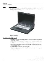
Page 10: ...ensured Notebook design dimensions weight optimal for use in confined spaces at the plant as well as when traveling High performance lithium ion battery with rated capacity of 90 Wh for extended cordless operation Housing made of magnesium alloy with soft plastic corners providing good protection for the electronics inside Powerful graphics controller with triple head function High resolution anti...

Page 11: ...a network without additional hardware through two full and independent Gigabit Ethernet interfaces WLAN corresponding to IEEE 802 11 ac Integrated Bluetooth in accordance with standard 5 0 Fast easily exchangeable SATA drive 4 USB 3 0 ports including 1 USB port with charging function for smartphones HDA High Definition Audio interface for sound Integrated Trusted Platform Module to TPM 2 0 standar...

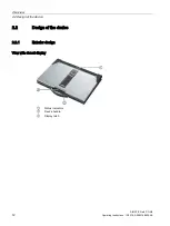
Page 12: ...2 2 Design of the device SIMATIC Field PG M6 12 Operating Instructions 12 2018 A5E43198909 AA 2 2 Design of the device 2 2 1 Exterior design View with closed display Status indicators Device handle Display latch ...

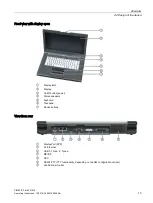
Page 13: ...9 AA 13 Front view with display open Display latch Display On off button power Stereo speakers Keyboard Touchpad Mouse buttons View from rear DisplayPort DPP 2 x Ethernet USB 3 1 Gen 2 Type A MPI DP DVI I RS232 TTY TTY functionality depending on the HW configuration variant Ventilation air outlet ...

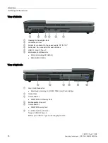
Page 14: ...J connection for audio devices USB 3 1 Gen 2 Type C Multimedia Card Reader for SD card including SD UHS II SMC SIMATIC MC View of right side Smart Card Reader for Smart card according to ISO IEC 7816 Smart Card Interface Optical drive Card reader for SIMATIC Micro Memory Card Exchangeable drive unit Card reader for SIMATIC Memory Card 2 x USB 3 0 ports with cover Top port USB 3 0 Type A Bottom por...

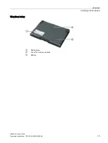
Page 15: ...Overview 2 2 Design of the device SIMATIC Field PG M6 Operating Instructions 12 2018 A5E43198909 AA 15 View from below Rating plate Cover for memory modules Battery ...

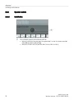
Page 16: ...09 AA 2 2 2 Operator controls 2 2 2 1 On off button The on off button power has the following functions Switch PG on off hold the button down for approximately 1 second the response depends on the Windows power option settings Switch PG off in the event of a fault hold down for more than 5 seconds ...

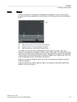
Page 17: ...t In contrast to a touch pad with a differentiated left and right mouse button the mouse buttons on this clickpad are integrated into the surface In this case the function of the left or right mouse button has been transferred to the two integrated mouse buttons Pressing lightly on the clickpad in the selected lower part of the area initiates a left or right mouse click The clickpad haptically pro...

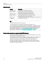
Page 18: ...e in the Windows Control Panel The technical principle used means that it is possible to make unintentional mouse clicks with the clickpad when it is used in an environment with EMC interference In such environments it is a good idea to use an external mouse Observe the information on electromagnetic compatibility in section Technical specifications Page 77 Problems during operation in an environm...

Page 19: ...e keyboard is divided into the following function groups Alphanumeric keyboard field with hotkeys Function keys Control keys Repeat function All the keys of the keyboard are equipped with a repeat function i e the character is repeated for as long as the key is pressed Keyboard labeling The keyboard comes with international and German labeling ...

Page 20: ... is displayed You can switch off the caps lock by pressing the shift key Num Lock key This toggles the emulated numerical keypad between alphanumeric keys and number keys The LED display lights up Scroll Lock Use this key to decide whether the cursor keys should move the cursor or the screen section this functionality is not supported by every program Start key under Windows The start key calls up...

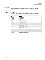
Page 21: ...ions Key Function Fn Home Cursor at start Fn End Cursor at end Fn ESC Disable PG Fn F1 Switch speaker on and off Fn F2 Control menu for the display monitor display Fn F3 Switch WLAN on and off Fn F4 Switch clickpad function mouse pointer and mouse buttons on and off Fn F5 Standby mode depending on the configuration of the Power Button in the Windows Power Options Fn F6 Hibernation mode depending o...

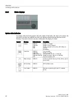
Page 22: ...when the display is closed Symbol Meaning Status indicator Description Battery GREEN ORANGE RED OFF Battery is charged Battery is being charged Battery capacity too low only with battery op eration No battery Operation GREEN ORANGE GREEN flashing ORANGE flashing OFF Line operation Battery operation Line operation device is in Standby Battery operation device is in Standby Device is switched off Ma...

Page 23: ...e status indicators of the keys light up briefly The keyboard is ready Symbol Meaning Status indicator Description Num Lock GREEN OFF Num Lock switched on Num Lock switched off Caps Lock GREEN OFF Caps Lock switched on Caps Lock switched off WLAN The WLAN status indicator is located to the right of the keypad LEDs and indicates whether WLAN is active Symbol Meaning Status indicator Description WLA...

Page 24: ...ion siemens com mcms pc based automation en industrial pc expansion_components_accessories Order accessories from the SIEMENS Industry Mall 1 Navigate to the Internet URL of the Industry Mall https mall industry siemens com 2 Log in with your customer data login on the top right 3 Select the user language 4 Navigate to the programming devices in the product catalog tree structure on the left Autom...

Page 25: ...nt please contact your service representative Repairs Only qualified personnel are permitted to repair the device WARNING Damage to property and personal injury Unauthorized opening and improper repairs can cause considerable damage to property or danger for the user System expansions Only install system expansion devices designed for this device The installation of other expansions can damage the...

Page 26: ...n open fire do not solder or open the cell body do not short circuit or reverse polarity do not heat up above 100 C follow the disposal instructions and protect against direct exposure to sunlight humidity and condensation ESD guidelines Modules containing electrostatic sensitive devices ESDs can be identified by the following label Strictly follow the guidelines mentioned below when handling modu...

Page 27: ... using the PG abroad If this is not the case purchase a power cable that complies with the local conditions Do not use connection adapters for electrical appliances in order to connect the device to them Transport Despite the fact that the device is of a rugged design its internal components are sensitive to severe vibrations or shock With just a few simple transport precautions you can help to cr...

Page 28: ...ts A user with administrator privileges has extensive access and manipulation options in the system Therefore ensure there are adequate safeguards for protecting the administrator accounts to prevent unauthorized changes To do this use secure passwords and a standard user account for normal operation Other measures such as the use of security policies should be applied as needed ...

Page 29: ...pose of the original packing material Keep it in case you have to transport the unit again Please keep the documentation in a safe place It is required for initial commissioning and is part of the device Check the delivery unit for any visible transport damage Check the delivery and your specially ordered accessories against the packaging list to ensure nothing is missing Please inform your local ...

Page 30: ...dentified with the help of the identification data in case of repairs or loss The figures below are examples The data of your device may differ from the data in these examples Rating plate The rating plate is located on the underside of the device Example COA label The COA label is located on the underside of the device Example COA label for the Microsoft Windows 10 operating system ...

Page 31: ...plate 6ES Serial number Rating plate S VP Microsoft Windows Product Key COA label Ethernet address 1 BIOS Setup Menu Advanced Peripheral Configuration Ethernet address 2 1 Enter the order number serial number and production status in the table above 2 Transfer the Microsoft Windows Product Key to the table This is always required to reinstall the operating system 3 Enter the Ethernet addresses in ...

Page 32: ...nd damage sensitive components Position the programming device to ensure comfortable operation and safety Position the programming device with its bottom on a flat surface and at a comfortable height and distance Ensure that a power outlet is easily accessible near your workplace Ensure that there is enough space for connecting peripherals Do not obstruct any ventilation slots when you position th...

Page 33: ...etc WARNING Operation only in grounded power supply systems The device is designed only to be used in grounded power supply systems TN systems to VDE 0100 part 300 or IEC 60364 3 It must not be used in ungrounded or impedance grounded power systems IT systems WARNING Danger of damage to the device or destruction of the battery Only use the supplied battery or an original spare part Information on ...

Page 34: ...nector 15 A min 125 V For countries other than the USA and Canada 230 V supply voltage This device is equipped with a safety tested power cord If you choose not to use this cable you must use a flexible cable of the following type At least 18 AWG 0 82 mm2 conductor cross section and 15 A 250 V connector The cable set must conform to the safety regulations of the country in which the devices are in...

Page 35: ... are possible with this cable To achieve baud rates higher than 1 5 Mbps you will need a 12 Mbps PROFIBUS connecting cable order number 6ES7901 4BD00 0XA0 Connecting the Field PG to an S7 automation system 1 Switch off your device 2 Plug the cable into the MPI DP inter face 3 Screw the connector into place 4 Insert the cable into the respective port on the CPU In the disturbed environment Bus con ...

Page 36: ...r to link to SIMATIC S7 The PROFIBUS software package is needed to link to S7 automation systems RS232 TTY interface COM1 You can connect the Field PG to a SIMATIC S5 programmable controller via the optional TTY interface You will need the SIMATIC STEP 5 V7 23 software to link to S5 programmable controllers WLAN You can link the Field PG to an Industrial Wireless LAN network using the integrated W...

Page 37: ...evices Strictly adhere to the specifications for peripheral equipment WARNING Equipotential bonding of the signal cable shields When you connect long signal cables particularly with connections between buildings make sure the signal cables are always integrated into the local equipotential bonding system connecting the cable shielding to the protective conductor Connecting a monitor You can also c...

Page 38: ... contacts are assigned differently The audio controller of the Field PG recognizes the assignment of the contacts of the UAJ connector depending on the connected audio device and is automatically configured You can connect the following audio devices to the UAJ connection Audio device with line out Audio device with line in Headphones Microphone Headset with headphones and microphone with the foll...

Page 39: ...irements for commissioning The power supply is connected or the battery is fully charged 5 2 Initial startup Commissioning the operating system Your device is delivered with preinstalled device drivers and SIEMENS software products After switching on the device for the first time you can make the following menu driven personnel settings Specify display language and region Create user account Requi...

Page 40: ...ly you must restore the operating system with the supplied Restore DVD set to achieve full operational reliability You can find additional information on this in Restoring operating system and partitions Page 70 1 Switch the device on 2 The operating system is set up automatically The device may restart multiple times during this process 3 Wait until you are prompted to select the language 4 Type ...

Page 41: ...wing areas Date time Region language Changing the system account and the standard user account settings You can change the settings for the display language region and formats of the system account for example the display language in the user login dialog and the settings of the standard user account default setting for new users The settings of the registered user are copied to the system account...

Page 42: ...tup program install the license or to install the license later with the Automation License Manager you are going to install If you want to transfer the license key later follow these steps 1 Close the Automation License Manager Locate the drive named License_Key in the left pane 2 Click the drive named License_Key This displays an overview of the license keys found on the license stick 3 Use a dr...

Page 43: ...WARNING Danger of damage to the device or destruction of the battery Only use the supplied battery or an original spare part Information on original spare parts for Field PGs is available in section Accessories Page 24 Disposal Lithium ion batteries can be recycled Their components can be used as raw materials for new batteries or other products A requirement for effective recycling is the collect...

Page 44: ... if for example the upper temperature limit for charging is exceeded You can check the battery charge level in Windows When the power supply is connected and the status indicator of the battery lights up green the battery is full and will not be charged any further Current consumption in battery operation You can reduce the off state battery power consumption of your device to the minimum by disab...

Page 45: ...ths after purchase of your PG it can still be charged and discharged A loss of capacity over time is technology dependent and as with all manufacturers of comparable devices it is excluded from the warranty In the case of a significant drop of efficiency we recommend that you replace the battery Use only Siemens original spare parts You should note the following with regard to the life span of the...

Page 46: ...batteries in section Rechargeable battery Page 43 Requirement The device is completely isolated from the line voltage Procedure 1 Turn the device over so that it is lying on a stable surface with its display unit closed 2 Release the battery cover on the bottom of the device 3 Open the battery cover in the direc tion of the arrow and if necessary remove the old battery Insert the new battery 4 Clo...

Page 47: ...s the on off button briefly Parameterize the change to the different operating states In Windows you can set parameters for the time interval and the actions for change to a different operating mode in the power options Select Control Panel All Control Panel Items Power Options Before changing the power options make a note of the factory settings if necessary Note Deactivating Hibernation or Stand...

Page 48: ... Optical drive This drive allows you for example to read the operating instructions on the supplied Manuales and Drivers DVD Information on burning data storage media CD RW or DVD RW NOTICE Danger of data loss Burning is permissible only in an undisturbed environment i e shock and vibration stress must be avoided Because of heavy fluctuation in the quality of CD Rs data may be corrupted in a burni...

Page 49: ...needle or a straightened paper clip for this Push it approx 2 3 mm into the hole The drive drawer will open Inserting or removing data storage media To prevent excessive force acting on the extended drive drawer hold it at the front panel when inserting or removing the data storage media After closing the drawer the data storage medium is initially tested and then the access display on the drive s...

Page 50: ... switched off The circuit is compliant with USB standard BC1 2 and also supports charging of Apple devices based on the so called divider mode method Devices charged in divider mode will only reach the maximum current in shutdown state If you also want to use the charging function in cordless operating mode while the device is shutdown activate the the corresponding function in the BIOS Setup dial...

Page 51: ...ound on the left and right of the device see section Exterior design Page 12 You can operate the following SIMATIC cards in the following card readers SIMATIC Memory Card SIMATIC Memory Card for S7 300 400 SIMATIC Memory Card for S7 400 long design SIMATIC Memory Card for S7 300 short design SIMATIC Micro Memory Card SIMATIC Micro Memory Card for S7 300 C7 ET200 SMC SIMATIC MC SIMATIC Memory Card ...

Page 52: ...or the SIMATIC Micro Memory Card is located on the right hand side of the device see section Modifying SIMATIC Micro Memory Cards Page 53 The Multimedia Card Reader is located on the left hand side of the device The contact areas of the card face downward When inserting the card pay attention to the correct positioning of the card To remove the card press it lightly towards the device The card is ...

Page 53: ... function of your SIMATIC programming software to read pro gram or erase the SIMATIC Micro Memory Card 4 End the programming function of your SIMATIC programming software 5 Remove the SIMATIC Micro Memory Card from the card reader NOTICE Do not insert or remove the module while it is in use Plugging in or removing the module while the module is being changed could damage the module Do not remove t...

Page 54: ... software to read program or erase the SIMATIC Memory Card 3 End the programming function of your SIMATIC programming software 4 Remove the SIMATIC Memory Card from the card reader NOTICE Do not insert or remove cards while in use Inserting or removing a card while it is in use could damage it The card may not be removed as long the status indicator is lit See section Status displays Page 22 Obser...

Page 55: ...9 AA 55 6 1 4 5 Editing smart cards You can read smart cards with an integrated chip such as plant ID cards with the Smart Card Reader The Smart Card Reader is located on the right hand side of the device When inserting the card pay attention to the correct positioning of the card The chip must face upward ...

Page 56: ...strator you have exactly the same access to files the printer and to the Internet with WLAN as with cable network Depending on the surrounding conditions you can create connections through walls or at distances in the open air of up to 100 m The on board network adapter operates based on the following standards The IEEE standard offers two modes of operation the ad hoc mode Peer to Peer and the in...

Page 57: ...tion in accordance with your WLAN and Bluetooth environment If possible do not bring the WLAN and Bluetooth connection in the vicinity of the following devices as the operation of these devices may result in faults or the complete failure of the WLAN and Bluetooth connection Microwaves Wireless video audio transmission systems Wireless telephones DECT CAUTION Risk of interference with pacemakers T...

Page 58: ...transfer a STEP 7 project from one PG to another To transmit in the SIMATIC Manager select File Archive or File Retrieve A detailed description of the procedure is given in section Steps for File Archiving Retrieval of the online help for STEP 7 Starting WinCC flexible Please note that a license key is required to use WinCC flexible In the Windows desktop click on the SIMATIC Manager icon or Click...

Page 59: ...rom a bootable ISO file made available by another PC SOL Serial over LAN You can redirect data of a serial interface to the network The function is used primarily for text based remote control of an AMT PC in console mode IDE redirection An ISO file contains a memory image of the content of a CD or DVD with ISO 9660 structure An ISO file can be implemented on the AMT PC for use as virtual DVD driv...

Page 60: ...d Platform Module The Trusted Platform Module TPM is a chip that adds security functions to your device This enables improved protection of the device against manipulation for example NOTICE Import restrictions for the Trusted Platform Module Some countries restrict the use of Trusted Platform Modules Use of Trusted Platform Modules in these countries is not permitted Observe all regulations of th...

Page 61: ...d that the device cannot get damaged 2 Close the display unit 3 Remove all connecting cables from the device 4 Place the PG with the display unit face down on an level surface NOTICE Observe the ESD guidelines The electronic components on the PCBS are highly sensitive to electrostatic discharge It is therefore vital to take precautionary measures when handling these components Refer to the ESD Gui...

Page 62: ...6 62 Operating Instructions 12 2018 A5E43198909 AA Removing a memory module 1 Remove the battery Page 46 2 Remove the screw Torx T6 that holds the cover 3 Remove the cover 4 Carefully push the two clamps to the side The memory module folds up 5 Pull the memory module out of the slot ...

Page 63: ... Carefully push the module downwards until the lock engages 3 Put the cover back over the slot and fasten this with the screw 4 Insert the battery again Page 46 and connect the device to the power supply system Note The memory modules must be seated firmly in their slots Faulty contact of the memory modules may lead to malfunction e g boot failure of the device Display of the current memory config...

Page 64: ...at are subject to wear in accordance with the intervals for replacement indicated in the table below Component Replacement interval Drives 3 years Backup battery 5 years 8 1 2 SSD kit SSD kits consist of the SSD unit please refer to the order documents for the capacity of the SSD a T8 Torx screwdriver and a transport and storage bag SSD kits are available with the following order numbers 6ES7791 2...

Page 65: ...ld PG M6 Operating Instructions 12 2018 A5E43198909 AA 65 SATA to USB 3 0 adapter With the SATA to USB 3 0 adapter order no 6ES7790 1AA01 0AA0 you can easily create an image of your system for backup purposes or as the basis for system specific installations See also Accessories Page 24 ...

Page 66: ...rmation about this can be found in section SSD kit Page 64 The device is not in Standby or Hibernate mode unsaved data might be lost or the device can get damaged The device is completely isolated from the line voltage The battery has been removed see section Using batteries Page 46 All connecting cables have been removed from the device Removing the SSD unit 1 Open the display 2 Remove both screw...

Page 67: ...oving hardware SIMATIC Field PG M6 Operating Instructions 12 2018 A5E43198909 AA 67 Inserting the SSD unit 1 Carefully slide the new SSD unit into the slot as far as it will go 2 Close the cover and secure it with the two screws See also ESD Guidelines Page 75 ...

Page 68: ...ou can find information on this on the Internet at SIEMENS Repair Service https support industry siemens com cs ww en sc 2154 NOTICE Risk of damage The lithium battery may only be replaced with an identical battery or with a type recommended by the manufacturer order no A5E00047601 WARNING Danger of explosion and the release of harmful substances Do not throw lithium batteries into an open fire do...

Page 69: ...rs 8 2 1 Updating the operating system We recommend updating the operating system as soon as relevant updates for it become available Requirements You have administrator rights for the system The device is connected to the Internet Procedure 1 Select Start Settings Update security Windows Update Check for update Windows determines the updates that are not installed 2 Then start the download and in...

Page 70: ... loss Files user settings as well as existing authorizations and license keys are lost when a restore is performed Back up your data before restoring 1 Insert the first DVD 1 x of the supplied Restore DVD set into the optical drive 2 Restart the device 3 Boot from the inserted DVD The Restore program from Siemens starts after a few seconds 4 Follow the instructions on the screen Note the following...

Page 71: ...Windows operating system is booted Internet Explorer 8 0 or higher is installed Scripts and ActiveX controls are enabled in the browser Procedure 1 Insert the supplied Manual and Drivers DVD into the optical drive 2 Start the START CMD script from this DVD 3 Select Software or Drivers in the index 4 Select the device and operating system 5 Select the desired software component or driver 6 Click on...

Page 72: ...nformation about SIMATIC IPC Image Partition Creator refer to the corresponding product documentation 8 5 Modifying the partitions We recommend the software tool SIMATIC IPC Image Partition Creator as of V3 5 1 for modifying partitions under Windows SIMATIC IPC Image Partition Creator can be ordered using the Siemens online ordering system https mall industry siemens com For more information about...

Page 73: ...ense agreements Certificates for USA and Canada Product safety The following approval is available for the device Underwriters Laboratories UL according to UL 62368 1 Second Edition and Canadian Standard CAN CSA C22 2 No 62368 1 14 Second Edition WLAN The integrated wireless LAN conforming to IEEE 802 11 a b g n ac is certified for Europe the USA and Canada RCM AUSTRALIA NEW ZEALAND This product m...

Page 74: ...dards Health EN 50566 Safety EN 62368 1 EMC EN 301 489 1 EN 301 489 17 Radio EN 300 328 EN 301 893 RoHS Directive This product meets the requirements of the RoHS Directive Restriction of Hazardous Materials 2011 65 EU Compliance with the directive was tested according to the following standard EN 50581 Declaration of conformity The EC declaration of conformity and the corresponding documentation a...

Page 75: ...y referred to as ESD devices This is also the international abbreviation for such devices Electrostatic sensitive modules are identified by the following symbol NOTICE Risk of overvoltage Modules that are sensitive to electrostatic discharge can be destroyed by voltages well below those that can be perceived by human beings Such voltages occur if you touch a component or electrical connectors of a...

Page 76: ...n be subjected to Basic protective measures against electrostatic discharge Ensure correct grounding When handling electrostatically sensitive devices ensure that your body working environment and any packaging are sufficiently grounded This prevents electrostatic charge Avoid direct contact As a general rule only touch electrostatically sensitive devices when otherwise unavoidable e g during main...

Page 77: ... DC 19 V Output current of the power supply unit DC Max 4 7 A Output power of power supply unit DC Max 90 W Standby power in battery operation Typically 1 5 W Lithium ion battery 9 cells with detection of charging condition Approx 8250 mAh 11 1 V with thermal switch and multi fuse recyclable chargeable up to 40 C high number of cycles for use in harsh environments low self discharge Noise emission...

Page 78: ...atic electricity 4 kV contact discharge according to IEC 61000 4 2 ESD 8 kV air discharge according to IEC 61000 4 2 ESD Immunity to RF interference 10 V with 80 amplitude modulation with 1 kHz from 150 kHz to 80 MHz according to IEC 61000 4 6 10 V m with 80 amplitude modulation with 1kHz 80 MHz to 1000 MHz according to IEC 61000 4 3 3 V m with 80 amplitude modulation with 1 kHz 1 4 GHz to 6 GHz a...

Page 79: ...s 100 shocks Storage transport Half sine 250 m s2 6 ms 1000 shocks Special features Quality assurance According to ISO 9001 Motherboard Processor Processor specifications are listed in your order docu ments RAM Expandable to 32 GB DDR4 SODIMM Drives SSD 2 5 SATA capacity specified in BIOS Optical drive DVD R RW Burner operation of the optical drive is only allowed in an undisturbed environment and...

Page 80: ...efective areas light and dark pixel Max 10 Audio Audio controller Realtek ALC255 UAA compatible Internal loudspeaker Maximum output power 2 x 1 W WLAN and Bluetooth WLAN is supported in the frequency ranges Bluetooth version WLAN standard according to IEEE standard IEEE 802 11a b g n ac Frequency ranges 2 4 GHz 5 0 GHz Connection range Up to 100 m Transmission rate Up to 1 73 Gbps Keyboard Variant...

Page 81: ...or external monitor max resolution 4096 x 2560 USB 1x USB 3 1 Gen 2 Type C left hand side of device Max 1 5 A 1x USB 3 1 Gen 2 Type A back of device Max 0 9 A 1 x USB 3 0 Type A right hand side of device top Max 0 9 A 1 x USB 3 0 Type A right hand side of device bot tom with charging function for smartphone Max 1 5 A PROFIBUS MPI interface 9 pin sub D socket Transmission speed 9 6 kBaud to 12 Mbau...

Page 82: ... Card Reader Programming interface for SIMATIC Memory Cards S5 and S7 400 SIMATIC Micro Memory Card Reader Programming interface for SIMATIC Micro Memory Card Multimedia Card Reader Interface for SMC mechanical as SD card programming function SD card including SD UHS II MMC Status indicators on the device Charge level Device status Access to SSD MPI DP S5 and S7 modules Num Lock Caps Lock WLAN act...

Page 83: ...tion 9 4 1 External interfaces DC In Power adapter socket This has the following charge USB 3 0 3 1 Type A Pin no Short designation Meaning Input output 1 VBUS 5 V fused Output 2 D Data line Input output 3 D Data line Input output 4 GND Ground 5 RX Data line Input 6 RX Data line Input 7 GND Ground 8 TX Data line Output 9 TX Data line Output ...

Page 84: ...D Data cable USB 2 0 Input output A7 D Data cable USB 2 0 Input output A8 Not assigned A9 VBUS 5 V fused Output A10 RX2 Data cable USB 3 0 Input A11 RX2 Data cable USB 3 0 Input A12 GND Ground B1 GND Ground B2 TX2 Data cable USB 3 0 Output B3 TX2 Data cable USB 3 0 Output B4 VBUS 5 V fused Output B5 VCONN Configuration channel Input output B6 D Data cable USB 2 0 Input output B7 D Data cable USB 2...

Page 85: ...ntial 8 DCD M5 Data carrier detect Input 9 TTY RxD Current loop receive Input 10 17 Not assigned 18 TTY TxD Current loop send Output 19 20 mA Potentially isolated power source 20 DTR S1 Data terminal ready Output 21 TTY TxD Current loop send Output 22 RI M3 Incoming call Input 23 25 Not assigned Gender changer for COM1 With the gender changer 25 pin 9 pin the COM1 V 24 AG port can be converted to ...

Page 86: ... 1 TX2N TDMS data 2 Output 2 TX2P TDMS data 2 Output 3 GND Ground 4 NC Not used 5 NC Not used 6 DDC CLK DDC clock Input output 7 DDC CLK DDC data Input output 8 VSYNC Vertical synchronizing pulse Output 9 TX1N TDMS data 1 Output 10 TX1P TDMS data 1 Output 11 GND Ground 12 NC Not used 13 NC Not used 14 5 V 5 V Output 15 GND Ground 16 MONDET Hotplug detect Input 17 TX0N TDMS data 0 Output 18 TX0P TD...

Page 87: ... ML_Lane1 DP data 1 Output 5 GND Ground 6 ML_Lane1 DP data 1 Output 7 ML_Lane2 DP data 2 Output 8 GND Ground 9 ML_Lane2 DP data 2 Output 10 ML_Lane3 DP data 3 Output 11 GND Ground 12 ML_Lane3 DP data 3 Output 13 CONFIG1 CAD Cable Adapter Detect Input 14 CONFIG2 Ground pull down 15 AUX_CH Auxiliary channel Bi directional 16 GND Ground 17 AUX_CH Auxiliary channel Bi directional 18 HPD Hot Plug Detec...

Page 88: ... rectly connected PLC is sending Input 5 M5EXT M5EXT return line GND of the 5 V power supply The current load caused by an external consumer connected between P5EXT and M5EXT must not exceed the maximum of 90 mA Output 6 P5 EXT P5EXT power supply 5 V of the 5 V power supply The current load caused by an external consumer connected between P5EXT and M5EXT must not exceed the maximum of 90 mA Output...

Page 89: ... D Input output S Shielding LED 1 OFF Lights up green Lights up orange 10 Mbps 100 Mbps 1 Gbps LED 2 Lights up green Flashes green Connection is up indicates activity UAJ You can connect various audio devices to the UAJ connection The audio controller socket recognizes the pin assignment of the connector depending on the connected audio device Information on connecting the audio devices can be fou...

Page 90: ...I DP The 6ES7901 0BF00 0AA0 cable is used to connect your PG to a SIMATIC S7 automation system Note the information in section Connect SIMATIC S7 or PROFIBUS Page 35 9 5 System resources Currently allocated system resources All system resources hardware addresses memory configuration allocation of interrupts DMA channels are assigned dynamically by the Windows OS depending on the hardware configur...

Page 91: ...tware CPU If a BIOS update of the PC is performed while SIMATIC software controller a SIMATIC WinAC for example is running the software CPU can malfunction resulting in communication interruptions or failures for example Other actions that put a heavy load on the PC hardware for example running hardware tests such as benchmarks can result in malfunctions of the software CPU Do not run a BIOS updat...

Page 92: ...9 6 2 Opening the BIOS selection menu Procedure 1 Reset the device warm or cold restart Depending on the device version the default settings can differ from the figures shown The following message appears briefly on the display at the end of the self test Press ESC for boot options 2 Press ESC to open the BIOS selection menu ...

Page 93: ...oot Maintenance Manager Boot Options Set boot order Driver Options Configure drivers Console Options Configure connected input device Boot from File Start from an EFI file Reset System Restore factory settings Administer Secure Boot Option 1 Configuration settings for starting the device in Administer Secure Boot mode The only software modules loaded are those that are known to be safe for the BIO...

Page 94: ...erent submenus Security Security functions e g setting a password Power Specify power management of CPU and the device Boot Determine boot options e g boot order Exit Save and exit see Exit menu The menus always have the same structure The figure below shows an example for the Main menu Device specific information is shown blurred Header The current version of the selected BIOS Setup is dis played...

Page 95: ...Field PG M6 Operating Instructions 12 2018 A5E43198909 AA 95 Help area Short help texts on the currently selected setup parame ters are displayed in the center right hand area Key assignment The key assignment for navigation in the BIOS Setup is found in the footer ...

Page 96: ...rs Load Optimal Defaults All setup parameters are reset to the safe default values Notice The existing Setup parameters are overwritten by this Load Custom Defaults The profile must be loaded with the custom Setup parameters Requirement The parameters are saved prior to this with Save Custom Defaults Notice All existing Setup parameters are overwritten during loading Write down the BIOS Setup sett...

Page 97: ...s Note Print out the table below and keep the pages in a safe place once you made your entries BIOS Setup default settings System parameters Defaults Custom entries Main System Time hh mm sss System Date MM DD YYYY Boot configuration Numlock On POST errors Never halt on errors Peripheral Configuration Internal COM 1 Enabled On board Ethernet 1 Enabled Ethernet 1 Address 00 1B 1B 41 42 7B exam ple ...

Page 98: ...assword Write Enabled USB Configure Disabled PET Progress Enabled Intel AMT SPI Protected Disabled Security TPM Operation No operation Supervisor Password Not installed User password Not installed Power on password Disabled User Access Level View Only Power USB charger Disabled Wake on LAN 1 Enabled Wake on LAN 2 Enabled Advanced CPU Control SW Guard Extensions SGX Software Controlled Select Owner...

Page 99: ...2018 A5E43198909 AA 99 Advanced CPU Control Turbo Mode Enabled C state Enabled Boot Quick Boot Enabled Quiet Boot Enabled Network Stack Disabled PXE Boot capability Disabled Add Boot Options Auto USB Boot Disabled EFI Device First Enabled Timeout 0 Legacy Boot Device Priority Normal Boot Menu Standard ...

Page 100: ... This can put the system in an undefined state This may damage the device and the plant 1 Print out the table in the next section General BIOS Setup settings 2 Enter your specific BIOS Setup setting in this table before you run a BIOS update 3 Start BIOS Setup after the BIOS update 4 Load the BIOS Setup default settings with F9 Setup Defaults Or use the BIOS Setup command Load Optimal Defaults in ...

Page 101: ...device follow these steps to install the update 1 Connect the device to the power supply 2 Copy the update to a USB memory stick 3 Reset the device warm or cold restart The following message appears briefly on the display at the end of the self test Press ESC for boot options 4 Press ESC to open the BIOS selection menu 5 Click the BIOS Update button 6 Follow the instructions on the screen Reboots ...

Page 102: ...rating system or application programs refer to the corresponding manuals On screen error messages On screen error message Meaning tip Operating system not found Possible causes No operating system installed Incorrect active boot partition Wrong boot drive settings in SETUP Keyboard controller error Controller error Contact your technical support team SMART failure detected on HDD Hard disk reports...

Page 103: ... 103 9 7 Boot mode and partitions in the delivery state Factory state for Windows 10 In the factory state Windows 10 boots in UEFI mode The following table lists the partitioning for data storage media 200 GB on delivery Partition Name Size File system First Boot 260 MB FAT32 Second MSR 128 MB None Third System Remainder NTFS not compressed ...

Page 104: ...le using the KVM server that is integrated in the firmware KVM enables access to IPCs with a corrupted or no operating system as the KVM server is integrated in the AMT hardware KVM enables you to reboot a remote computer and make changes to its BIOS settings Remote power management SIMATIC IPC with Intel AMT can be switched on and off or restarted using another PC IDE redirection An image on the ...

Page 105: ...l notes 9 8 3 Enabling Intel AMT basic configuration For security reasons Intel AMT is not enabled on new devices The Management Engine ME is always active Procedure 1 If necessary first reset Intel AMT to the default status 2 To open the BIOS selection menu press the ESC key while the device is booting 3 Open the BIOS Setup using the Setup Configuration Utility SCU 4 Select the Active Management ...

Page 106: ...alid in the string but do not increase the complexity of the password Note If the password is no longer available you must reset the Intel AMT to the default settings Backup the password to protect it against loss 5 Switch to the Intel R AMT Configuration submenu and enable Manageability Feature Selection 6 Switch to the Intel R ME General Settings submenu and enable access via the network with Ac...

Page 107: ...s settings in the management engine MEBx are deleted Correct operation in the plant may be at risk Note down all the settings in the MEBx Make the settings again as necessary following Unconfigure 1 Enable the Unconfigure ME entry in Advanced Active Management Technology Support in the BIOS 2 Exit the BIOS with the F10 key Save and Exit The AMT PC restarts 3 After the restart a user prompt appears...

Page 108: ...nd line in Windows using ipconfig and in UNIX using ifconfig If the AMT server and operating system do not use the same network address ask your network administrator for the address you have been assigned 9 8 6 Forcing user consent When a connection to the AMT PC is established the KVM viewer may prompt the user to enter a six figure code This code is displayed on the screen of the AMT PC The use...

Page 109: ...iemens com sitrainworld AppLang en Industry Mall https mall industry siemens com When contacting your local representative or Technical Support please have the following information at hand MLFB of the device BIOS version for industrial PC or image version of the device Other installed hardware Other installed software Current documentation Always use the current documentation available for your p...

Page 110: ...p menu Although the BIOS setting is OK the time and data are still wrong The backup battery is dead In this case please contact your technical support team USB device not responding The operating system does not support the USB ports Enable USB Legacy Support for the mouse and keyboard For all other devices you will need USB drivers for the specific operating system The following message appears o...

Page 111: ...hat the transmission mode of all network components is set up in accordance with the IEEE 802 11 a b g n or ac standard The spatial arrangement of the network components can also negatively influence the transmission The distances between the components should be as short as possible Masonry or reinforced concrete walls have a negative effect on the transmission performance and can under some circ...

Page 112: ... symbols on your device may vary in some details from the symbols shown in the following tables B 2 Safety Symbol Meaning Symbol Meaning Warning observe the supplied docu mentation Lock is closed Attention radio equipment Lock is open Disconnect the power plug before opening Opening for Kensington lock Attention ESD Electrostatic sensitive device Warning of hot surface B 3 Operator controls Symbol...

Page 113: ...d more information in the operating instructions for your device Symbol Meaning Symbol Meaning Approved for Australia and New Zea land Marking for the Eurasian Customs Union Approved for China Test mark of Factory Mutual Re search CE markings for European countries Marking of Federal Communications Commission for the USA EFUP Environment Friendly Use Period marking for China Approved for Korea Tes...

Page 114: ...tor terminal PS 2 keyboard interface Connection for functional earthing equipotential bonding line Multimedia Card Reader DisplayPort interface Smart Card Reader DVI D interface Line In LAN interface not approved for con necting WAN or telephone Line Out Serial interface Microphone input USB port Universal Audio Jack USB 2 0 HiSpeed interface Headphone output USB 3 0 super speed port USB 3 1 Super...

Page 115: ...nadian Standards Association Canadian organization for tests and certifications according to own or binational standards with UL USA standards CTS Clear To Send Clear to send DC Direct Current DC current DCD Data Carrier Detect Data storage medium signal detection DPP DisplayPort High performance digital monitor interface DQS Deutsche Gesellschaft zur Zertifizierung von Qualitätsmanagement mBH DSR...

Page 116: ...ll RTS Reliable Transfer Service Request to send RxD Receive Data Data transfer signal SATA Serial Advanced Technology Attachment SMART Self Monitoring Analysis and Reporting Technology Fault diagnostic program for the drive SSD Solid State Drive Storage medium not volatile S VP Serial number of the device TFT Thin Film Transistor Type of LCD flat screen TTY Tele Type Asynchronous data transfer Tx...

Page 117: ... key 20 Card reader Status indicator 22 Certificate of Authenticity 40 Certificates 73 Clickpad with integrated mouse buttons 17 COA label Certificate of Authenticity COM1 port 36 81 Connecting 33 Peripheral equipment 37 Connecting an audio device to a UAJ socket 38 to a USB socket 37 Continue 93 Creating an image 72 D Data exchange 36 Declarations of Conformity 74 Degree of protection 77 Device u...

Page 118: ...36 MPI DP 13 Pin assignment DVI I 86 PROFIBUS 36 PROFIBUS MPI 81 RS232 TTY COM1 13 36 RS485 81 USB 3 1 Gen 2 USB 3 1 Gen 2 UAJ 14 USB 81 USB 3 0 Type A with charging function 14 Interrupt allocation 90 IT communication 36 K Keyboard Status indicator 23 Keyboard arrangement 19 Keyboard labeling 19 L Lithium battery Battery Localized information 34 M Manuals 8 Mass storage Status indicator 22 MEBx I...

Page 119: ...R Removing Memory modules 62 Repair service 68 Repairs 25 Replacing the SSD unit 66 RoHS Directive 74 RS232 interface 36 81 RS485 interface 81 RTTE Directive 74 S S5 cabling 90 90 S7 cable 90 90 Safety instructions 25 SATA to USB 3 0 adapter 65 SD card Card reader 14 Edit 52 Technical specifications 82 Serial interface 81 Pin assignment 85 Serial number 31 Setup Utility 93 SIMATIC MC SMC SIMATIC M...

Page 120: ...Trusted Platform Module Transport precautions 27 Troubleshooting FAQs 110 Troubleshooting WLAN 18 Trusted Platform Module 60 TTY interface 36 81 U UAJ 38 Pin assignment of the jack 89 UEFI mode 103 Unpacking Unpacking the device 29 Update Operating system 69 USB 81 USB socket with charging function 50 Technical specifications 81 Using rechargeable batteries 46 W Weight 77 WinCC flexible Starting 5...

Reviews: