Installation
4-13
Distributed I/O Device ET 200M
EWA-4NEB780600602-06
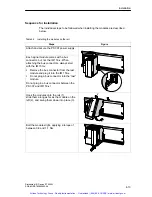
Sequence for Installation
The individual steps to be followed when installing the modules are described
below.
Table 4-3
Installing the modules on the rail
Steps
Figure
Attach and secure the PS 307 power supply.
Each signal module comes with a bus
connector, but not the IM 153-x. When
attaching the bus connectors, always start
with the IM 153-x:
Remove the bus connector from the last
module and plug it into the IM 153-x.
Do not plug a bus connector into the ”last”
module.
Do not plug in a bus connector between the
PS 307 and IM 153-x!
ET
–
0042
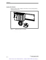
Hook the modules onto the rail (1),
slide them along as far as the module on the
left (2), and swing them down into place (3).
2
ET
–
0043
1
3
Bolt the modules tight, applying a torque of
between 0.8 and 1.1 Nm.
ET
–
0045
Artisan Technology Group - Quality Instrumentation ... Guaranteed | (888) 88-SOURCE | www.artisantg.com


