background image

Chapter 2

Installing the Base Station

RUGGEDCOM WIN7235

Installation Guide

12

Mounting the Base Station to a Pole

Section 2.6.2

Mounting the Base Station to a Pole

The base station can be attached to any pole (or pipe) with a 44.45 to 254 mm (1.75 to 10 in) diameter.
To mount the base station to a pole, do the following:
1. Attach the base station to the mounting bracket. For more information, refer to 

Section 2.6.3, “Assembling

the Base Station and Mounting Bracket”

.

2. Liberally apply an anti-corrosion spray to all galvanized steel components, including mounting brackets, nuts,

washers and screws.

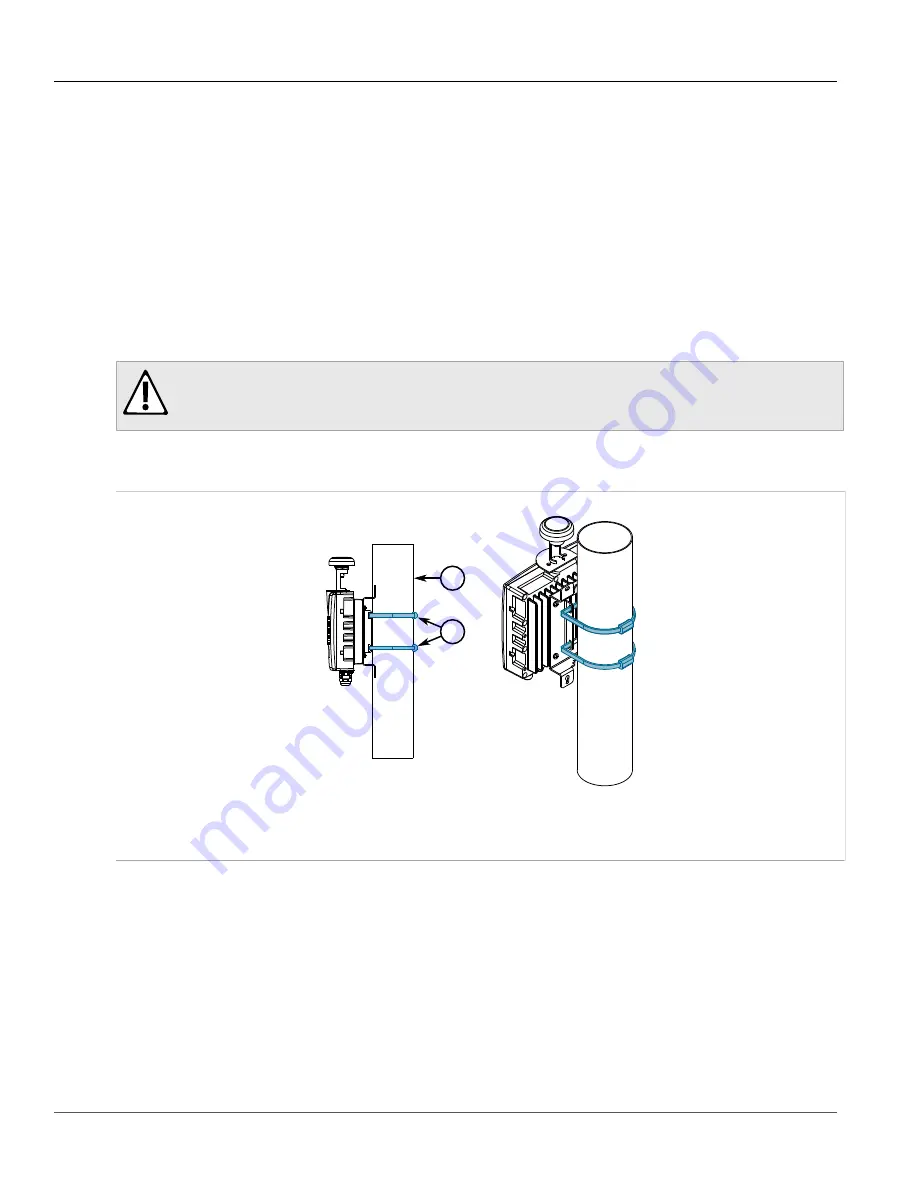
3. Thread two steel band straps through the top and bottom slots in the mounting bracket.
4. Select a mounting location on the pole.

CAUTION!

Environmental hazard – risk of damage due to the ingress of water, dirt or debris. Make sure the

base station is oriented with the interface connections facing down.

5. Lift the base station and mounting bracket assembly and align it with the selected mounting location on the

pole.

2

1

Figure 4: Securing the Base Station and Mounting Bracket Assembly to a Pole

1.

 Pole   


2.

 Steel Band Strap

6. Wrap the bands around the pole, lock the ends together, and then tighten the screws with a 5/16 socket head

wrench. The screws must be tight enough to prevent the base station and mounting bracket from moving.

7. Liberally apply an anti-corrosion spray to all exposed screw threads.

Section 2.6.3

Assembling the Base Station and Mounting Bracket

To assemble the base station and mounting bracket together, do the following:
1. Make sure the mounting bracket is standing on its base.

Summary of Contents for RUGGEDCOM WIN7235

Page 1: ...RUGGEDCOM WIN7235 Installation Guide 01 2018 RC1175 EN 01 Preface Introduction 1 Installing the Base Station 2 Technical Specifications 3 Dimension Drawings 4 Certification 5 ...

Page 2: ... that you regularly check for product updates For the secure operation of Siemens products and solutions it is necessary to take suitable preventive action e g cell protection concept and integrate each component into a holistic state of the art industrial security concept Third party products that may be in use should also be considered For more information about industrial security visit http ww...

Page 3: ... Station 10 2 6 1 Mounting the Base Station to a Wall or Tower 11 2 6 2 Mounting the Base Station to a Pole 12 2 6 3 Assembling the Base Station and Mounting Bracket 12 2 7 Installing Antennas 13 2 7 1 Installing an RF Antenna 14 2 7 2 Installing an External GPS Antenna 15 2 8 Grounding the Base Station 16 2 9 Connecting Power and Data 16 2 9 1 Connecting to a RUGGEDCOM RP100 or RP110 17 2 9 2 Con...

Page 4: ... 27 3 2 Power Supply Requirements 27 3 3 Radio and Modem Specifications 28 3 4 Operating Environment 28 3 5 Mechanical Specifications 29 3 6 IDU to ODU Cable Specifications 29 Chapter 4 Dimension Drawings 31 Chapter 5 Certification 33 5 1 Approvals 33 5 1 1 MET Laboratories 33 5 1 2 CSA 34 5 1 3 European Union EU 34 5 1 4 TÜV Rheinland 35 5 1 5 Other Approvals 35 5 2 EMC and Environmental Type Tes...

Page 5: ...stallation practices Personnel unfamiliar with safe installation procedures WiMAX technologies or service procedures should not rely on this guide for comprehensive guidance CONTENTS Alerts Related Documents Training Customer Support Alerts The following types of alerts are used when necessary to highlight important information DANGER DANGER alerts describe imminently hazardous situations that if ...

Page 6: ... with domain knowledge in the utility transportation and industrial markets allows Siemens to provide training specific to the customer s application For more information about training services and course availability visit https www siemens com ruggedcom or contact a Siemens Sales representative Customer Support Customer support is available 24 hours 7 days a week for all Siemens customers For t...

Page 7: ... Installation Guide Preface Customer Support vii Contact a local Siemens representative from Sales Technical Support Training etc Ask questions or share knowledge with fellow Siemens customers and the support community ...

Page 8: ...Preface RUGGEDCOM WIN7235 Installation Guide viii Customer Support ...

Page 9: ...613 IEC 61850 3 Class 1 Div 2 ATEX Zone 2 MIL STD 810F 509 4 salt fog Long Range Transmit and receive diversity combined with high power for improved reach and NLOS Non Line Of Sight performance High Bandwidth RUGGEDCOM WIN has two built in radios operating on the same frequency simultaneously MIMO or Multiple Input Multiple Output to increase bandwidth up to 40 Mbps and spectral efficiency Lowest...

Page 10: ... 802 16e standard and WiMAX Forum Wave2 MIMO certification GPS synchronization Backbone Ethernet connectivity via a 10 100Base T network interface Fixed and mobile subscriber station support 3 5 MHz 5 MHz 7 MHz and 10 MHz channel bandwidth support MIMO 2 2 support Non Line of Sight NLOS Small footprint and light weight enables simple installation and deployment by a single person Antennas 2 N Type...

Page 11: ...terfacing directly with the base station and accessing low level management functions For more information about this port refer to the RUGGEDCOM WIN Base Station User Guide CAUTION Security hazard risk of unauthorized access and or exploitation Restrict access to the serial console port to authorized personnel only ANT 1 and ANT 2 Ports N type female ports for connecting RF Radio Frequency antenn...

Page 12: ...Chapter 1 Introduction RUGGEDCOM WIN7235 Installation Guide 4 Description ...

Page 13: ...sk of serious personal injury and or damage to equipment Installing the RUGGEDCOM WIN7235 can pose a serious safety hazard Be sure to take precautions to avoid the following Exposure to high voltage lines during installation Falling when working at heights or with ladders Injuries from dropping tools Contact with AC wiring power system connection IMPORTANT Only certified personnel should be permit...

Page 14: ...thout waterproof sealing or if the sealing is removed from the connections CONTENTS Section 2 1 General Procedure Section 2 2 Unpacking the Base Station Section 2 3 Required Tools and Materials Section 2 4 Site Preparation and Precautions Section 2 5 Installing the Base Station in Hazardous Locations Section 2 6 Mounting the Base Station Section 2 7 Installing Antennas Section 2 8 Grounding the Ba...

Page 15: ...ase station is grounded For more information refer to Section 2 8 Grounding the Base Station 9 Connect the base station to a power source and the network For more information refer to Section 2 9 Connecting Power and Data 10 Seal all cable connections For more information refer to Section 2 10 Weatherproofing the Base Station 11 Configure the base station For more information refer to Section 2 12...

Page 16: ...ighest point possible Reception will increase according to the height of the antenna s Mount the antenna s in a place with as few obstructions as possible between the antenna s and the planned service area To avoid interference mount the antenna s and base station as far as possible from other antenna s and base stations Keep the cable from the base station to the antenna s as short as possible an...

Page 17: ...ays wear the appropriate Personal Protective Equipment PPE for the task including but not limited to rubber boots rubber gloves hard hat harness and lanyard etc Always use a ladder made of a non conductive material such as wood or fiberglass Do not use a metal ladder Always work under favorable conditions Do not work on wet or windy days If the base station or antenna begins to drop step away imme...

Page 18: ...lass I Division 2 Groups A B C D T4 Figure 2 Compliance Label Example Section 2 6 Mounting the Base Station The base station is designed to be mounted to a wall pole or tower DANGER Electrocution hazard risk of death or serious injury Make sure the distance between the base station and nearby power lines meets the minimum requirements established by local standards CAUTION Crushing hazard risk of ...

Page 19: ... mounting bracket from the wall tower 6 Using a 8 mm 5 16 in drill bit suitable for the building material drill holes at the marked locations 7 Insert a 8 mm 5 16 in wall anchor into each mounting hole 8 Attach the base station to the mounting bracket For more information refer to Section 2 6 3 Assembling the Base Station and Mounting Bracket CAUTION Environmental hazard risk of damage due to the ...

Page 20: ...unting location on the pole CAUTION Environmental hazard risk of damage due to the ingress of water dirt or debris Make sure the base station is oriented with the interface connections facing down 5 Lift the base station and mounting bracket assembly and align it with the selected mounting location on the pole 2 1 Figure 4 Securing the Base Station and Mounting Bracket Assembly to a Pole 1 Pole 2 ...

Page 21: ...l GPS antenna It also supports an external Radio Frequency RF antennas and omni directional or directional Global Positioning System GPS antennas When selecting the ideal location for an antenna consider the following recommendations Mount the antenna at the highest possible point to improve reception Select an area where there are few obstacles between the antenna and the planned coverage area or...

Page 22: ...d in time and according to the regulations set by the FCC or the regulations relevant to the country of installation IMPORTANT The antenna installation must be as per Article 810 of the NEC Of particular note is the requirement that the grounding conductor not be less than 10 AWG Cu The scheme should be either in accordance with UL 96 and 96A Lightning Protection Components and Installation Requir...

Page 23: ...tenna to the base station must not exceed 22 m 72 ft in length otherwise it may act as an antenna itself and generate interference Only use the CAT 5 cable provided with the base station To install an external GPS antenna do the following IMPORTANT The antenna installation must be as per Article 810 of the NEC Of particular note is the requirement that the grounding conductor not be less than 10 A...

Page 24: ... a 10 AWG cable DANGER Electrocution hazard risk of death or serious injury The system must be properly grounded to protect against power surges and accumulated static electricity It is the installer s responsibility to install this base station in accordance with the local electrical codes To ground the base station do the following 1 Assemble the ground connection as shown 1 3 5 4 2 1 2 Figure 8...

Page 25: ...EDCOM WIN7235 The RUGGEDCOM RP100 and RP110 meet a wider temperature and voltage range than the standardRUGGEDCOM WIN1010 When the base station is connected to a RUGGEDCOM RP100 or RP110 make sure there is a solid connection between the lightning protector and the base station The following illustration details a typical installation NOTE A shielded cable must be used and connected to local ground...

Page 26: ...equired ODU I F A 10 100Base T RJ45 copper Ethernet Power over Ethernet port that provides data and power to the base station A custom CAT5 e cable is required CAUTION Electrical hazard risk of damage to equipment The power cord provided with the data adapter is safety certified according to national rules Do not use a power cord that has not been approved by Siemens for use with the data adapter ...

Page 27: ...tween the data adapter and the 110 220 VAC mains 7 Verify the LEDs on the data adapter are green indicating the data adapter is providing power and data to the base station LED Color Description PWR Green Input power is connected LAN Green LAN link activity display Section 2 9 3 Assembling the PoE Connector A custom PoE cable with a special RJ45 connector is required to connect a PoE injector to t...

Page 28: ...n wire 38 mm 1 5 in 1 2 Figure 11 Cutting the Jacket 1 Wire Jacket 2 Foil 3 Fold the foil back over the wire jacket 1 2 3 Figure 12 Folding Back the Foil 1 Foil 2 Twisted Pair Wires 3 Drain Wire 4 Bend the drain wire back over the jacket 3 1 2 Figure 13 Bending the Drain Wire 1 Foil 2 Drain Wire 3 Twisted Pair Wires 5 Partially untwist each wire pair making sure to retain a half twist at the end ...

Page 29: ...RTN TP3 7 Slide the wires into the loading bar and then pull the loading bar down until its face is 16 mm 0 63 in from the wire jacket If necessary use pliers to hold the wires while pulling the loading bar 1 2 2 1 1 3 4 Figure 16 1 Loading Bar 2 Wires 3 Pin 1 4 Pin 8 8 Trim the wires until they are flush with the face of the loading bar 9 Insert the wires and loading bar into the plug body Make s...

Page 30: ...ten the compression nut to 0 56 N m 5 In lbs 18 Use a network cable tester to check for continuity opens and shorts across the cable assembly including the drain wire Section 2 9 4 Installing the Hazardous Location Kit An approved surge suppression unit is required when the base station is installed in a hazardous location The RUGGEDCOM WIN7235 is certified for installation in Class I Division 2 G...

Page 31: ... The AC power cable must meet the following specifications Consist of 3 wires Minimum 18 AWG Less than 4 5 m 14 7 ft long Safety certified according to national rules 4 Connect the open ended AC power cable to the power supply unit Section 2 10 Weatherproofing the Base Station This section describes how to protect the base station from the ingress of harmful moisture dirt and debris that can lead ...

Page 32: ...ith a clean lint free cloth 2 Spray the cable end and connector with SCC3 conformal coating and allow them to dry fully approximately 3 to 5 minutes depending on the ambient temperature 3 Apply cold shrink or self amalgamating tape to the connector end For information about how to apply these types of seals refer to Section 2 10 2 Applying Cold Shrink Tubing or Section 2 10 3 Applying Self Amalgam...

Page 33: ...tly wrap the remainder of the tape down the cable making sure the tape overlaps with each pass 4 Repeat the previous steps to apply a second layer of tape Section 2 11 Connecting to the Base Station The following describes the various methods for accessing the RUGGEDCOM WIN console and Web interfaces on the base station For more detailed instructions refer to the RUGGEDCOM WIN User Guide for the b...

Page 34: ...UGGEDCOM WIN7235 Accessing the Web Interface The access the Web interface for RUGGEDCOM WIN do the following 1 Connect a PC to the switch router that is on the same network as the base station 2 Open a browser and access the base station via its IP address The factory default IP address is 192 168 100 100 24 Section 2 12 Configuring the Base Station Once the base station is installed and connected...

Page 35: ...fications Section 3 1 Power Supply Specifications Power Input Maximum Consumption 85 to 265 VAC 85 to 264 VAC a 10 to 60 VDC 88 to 300 VDC 25 W a RUGGEDCOM RP100 or RP110 Section 3 2 Power Supply Requirements The RUGGEDCOM WIN7235 requires an external power supply that meets the following requirements Power Supply Rated Input Power Rated Output Power RUGGEDCOM WIN1010 100 to 240 VAC 50 to 60 Hz 1 ...

Page 36: ... External Antenna s N Connect female 50 Ω Output Power Average 2 x 27 dBm Size of Fast Fourier Transform FFT Channels 1024 512FFT Type of Modulation QPSK 16 QAM 64 QAM Type of Error Compensation FEC Convolution Code Turbo Code Dynamic Range Receiver 60 to 100 dBm Dynamic Range Transmitter 12 to 27 dBm Section 3 4 Operating Environment The RUGGEDCOM WIN7235 can operate under the following environme...

Page 37: ... VW 1 Description Applications Outdoor installations fixed or portable installations digital distribution frames in transmission stations outdoor installations in harsh environments General Construction Custom made cable designed specially for wireless systems meeting the requirements of CAT 5e per ANSI TIA EIA 568 B 2 and IEC 61156 5 The cable contains 4 twisted pairs cabled foil tape shielded an...

Page 38: ...ternal Diameter 8 mm 0 3 in Total Number of Wires 8 Standards Compliance Flammability Rating IEC 60332 UL1581 VW 1 Standards IEC 61156 TIA EIA 568 Performance Frequency Range 1 to 100 MHz Impedance 100 Ω DC Resistance 93 Ω km nominal Maximum DC Resistance 95 Ω km 20 C Maximum Capacitance Unbalance 1 6 pF m Velocity of Propagation 68 nominal Maximum Propagation Delay Skew 35 ns 100m Dielectric Stre...

Page 39: ...allation Guide Chapter 4 Dimension Drawings 31 Dimension Drawings NOTE All dimensions are in millimeters unless otherwise stated 285 5 19 9 83 2 228 4 85 4 46 1 Figure 20 RUGGEDCOM WIN7235 Dimensions without Mounting Bracket ...

Page 40: ...Chapter 4 Dimension Drawings RUGGEDCOM WIN7235 Installation Guide 32 112 5 215 0 201 0 16 3 106 0 51 0 Figure 21 RUGGEDCOM WIN7235 Dimensions with Mounting Bracket ...

Page 41: ...Laboratories Section 5 1 2 CSA Section 5 1 3 European Union EU Section 5 1 4 TÜV Rheinland Section 5 1 5 Other Approvals Section 5 1 1 MET Laboratories This base station meets the requirements of the following standards ANSI ISA 12 12 01 CSA C22 2 No 213 Nonincendive Electrical Equipment for Use in Class I and II Division 2 and Class III Divisions 1 and 2 Hazardous Classified Locations EN 60079 0 ...

Page 42: ...rer que l emplacement est désigné non dangereux Section 5 1 2 CSA This base station meets the requirements of the following Canadian Standards Association CSA standards CAN CSA C22 2 No 60950 1 07 A1 2011 A2 2014 Information Technology Equipment Safety Part 1 General Requirements Bi National Standard with UL 60950 1 CAN CSA C22 2 No 60950 22 07 GI1 2012 Information Technology Equipment Safety Part...

Page 43: ...CE marking and can be used throughout the European community A copy of the CE Declaration of Conformity is available from Siemens Canada Ltd For contact information refer to Contacting Siemens Section 5 1 4 TÜV Rheinland This base station is certified by TÜV Rheinland to meet the requirements of the following standards UL 60950 1 2007 R10 14 Information Technology Equipment Safety Part 1 General R...

Page 44: ...al 65 C 149 F 16 Hour Dwell IEC 60068 2 1 IEC 61850 3 5 2 Low Temperature Storage 40 C 40 F 16 Hour Dwell IEC 60068 2 2 IEC 61850 3 5 2 High Temperature Storage 65 C 149 F 16 Hour Dwell IEC 60068 2 30 IEEE 61850 3 5 2 Humidity Operational 95 at 55 C 131 F for 96 Hours IEC 60068 2 30 IEEE 61850 3 5 2 Humidity Storage 95 at 55 C 131 F for 96 Hours Mechanical Environmental Conditions IEC 60068 2 27 I...

Page 45: ...Storage 85 C 185 F 16 Hour Dwell IEC 60068 2 30 IEEE 1613 4 1 3 Humidity Storage 95 at 55 C 131 F for 96 Hours Mechanical Environmental Conditions IEEE 1613 10 Shock Drop 1 m 3 3 ft 1 Fall per Axis IEC 60068 2 6 IEEE 1613 10 Vibration 2 g 32 ft s 2 10 150 Hz per Axis Power Input IEC 61000 4 11 IEEE 1613 5 1 Voltage Variations 38 4 to 56 V EMC IEC 61000 4 12 IEEE 1613 7 3 1 IEEE C37 90 1 Oscillator...

Page 46: ...Chapter 5 Certification RUGGEDCOM WIN7235 Installation Guide 38 EMC and Environmental Type Tests ...

Reviews: