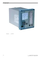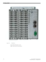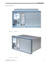
Size 12 Withdrawn
i
i
NOTE
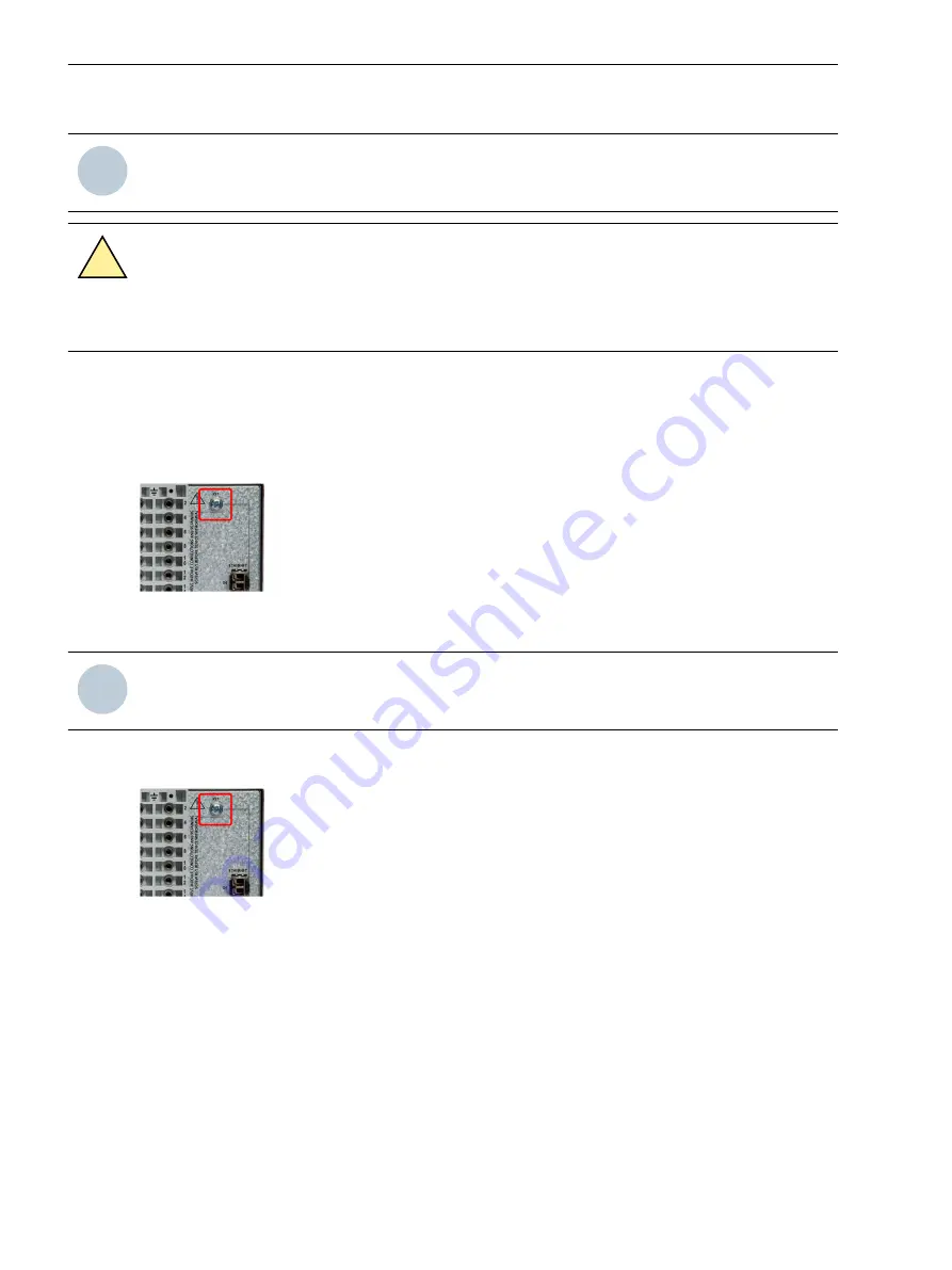
The rear retaining screw must be removed to allow withdrawal of the device from its case.
!
DANGER
Element Withdrawn
²
Do not insert anything into the case after withdrawing the element.
Contacts in the case ensure that the CT circuits and normally closed contacts are short-circuited when the
device is removed. It is recommended to apply external CT shorting and isolate external connections if the
case is wired in service e.g. using appropriate external isolation links. The removed device should not be
carried using the fascia levers, it should be held by the top and bottom plates and exposed PCB’s should not be
touched. The device should be protected from damage, handled with care and not exposed to contamination.
The device should be re-inserted into the case without the use of excessive force.
[sc_7SR5_size6_RetainingScrew, 1, en_US]
Figure 3-16
Retaining Screw
i
i
NOTE
Remove RS485 connector and ethernet cables if connected.
To withdraw the device from the case loosen both captive screws, then pull the levers as shown in the
following figures.
[sc_7SR5_size6_RetainingScrew, 1, en_US]
Figure 3-17
Retaining Screw
Handling of the Device
3.2 Withdrawing the Device Element
36
Reyrolle 7SR5, Operating, Manual
C53000-B7040-C013-1, Edition 05.2021
Summary of Contents for Reyrolle 7SR5
Page 6: ...6 Reyrolle 7SR5 Operating Manual C53000 B7040 C013 1 Edition 05 2021 ...
Page 10: ...10 Reyrolle 7SR5 Operating Manual C53000 B7040 C013 1 Edition 05 2021 ...
Page 40: ...40 Reyrolle 7SR5 Operating Manual C53000 B7040 C013 1 Edition 05 2021 ...
Page 76: ...76 Reyrolle 7SR5 Operating Manual C53000 B7040 C013 1 Edition 05 2021 ...
Page 114: ...114 Reyrolle 7SR5 Operating Manual C53000 B7040 C013 1 Edition 05 2021 ...

