background image

3/14 

Siemens 

Room Temperature Controllers 

N3057en 

Building Technologies 


2014-10-28 


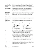
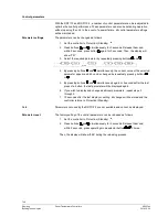
When external operating mode changeover is activated, the controller switches to 
Economy (Energy saving)


mode. In this operating mode, the relevant setpoints of 

heating or cooling are maintained. These setpoints can be adjusted via control 
parameters P01 and P02. The default fan speed in Economy (Energy saving)


mode is 

automatic fan. 

When the controller is in Protection (Standby) mode  , the relevant setpoints of 
heating or cooling are maintained. These setpoints can be adjusted via control 
parameters P03 and P04. Factory setting of both setpoints is OFF, which means that 
the controller is not activated when in Protection (Standby) mode. 

To avoid damage due to moisture in very warm and humid climatic zones resulting from 
lack of air circulation in Economy (Energy saving)


mode, the fan can be kept running all 

the time (e.g. in hotel rooms during unoccupied periods), when setting parameter P20 
to “ON in dead zone”. In this case, the fan keeps running at minimum fan speed 1. 


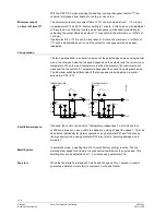
Control sequences 

Used in conjunction with a valve, either for heating / cooling with changeover, heating 
only or cooling only. 

Used in conjunction with a 1-stage compressor for cooling only or heating only. 
 
Heating mode 

Cooling mode 


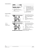
T[°C] 

Room temperature 

SDH 

Switching differential “Heating” 

Room temperature setpoint  

SDC 

Switching differential “Cooling” 

Y11 

Control output “Valve” or “Compressor” 


The valve or compressor receives the 

OPEN

 command via control output Y11 when 

1.  the acquired room temperature lies by half the switching differential below the 

setpoint (heating mode) or above the setpoint (cooling mode), and 

2.  control output Y11 was not energized for more than the “Minimum output off time” 

(factory setting 1 minute, adjustable via parameter P16) 

The valve or compressor receives the 

CLOSE

 command via control output Y11 when 

1.  the acquired room temperature lies by half the switching differential above the 

setpoint (heating mode) or below the setpoint (cooling mode), and 

2.  control output Y11 was energized for more than the “Minimum output on time”; 

(factory setting 1 minute, adjustable by parameter P15) 


Control output Y12 delivers a control command which is inverted to the control 


command at output Y11 and which can be used for normally open valves. 

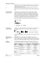
With the RDF110, the changeover between cooling and heating takes place either 
automatically via a heating / cooling changeover sensor or a remote changeover 
switch. If the controller was set to ”Cooling only” or ”Heating only”, changeover will not 
be possible (parameter P22, factory setting ”Cooling only”). 

Economy (Energy 

saving) mode    

(only with RDF110 and 
RDF110/IR) 

Protection (Standby)  


Avoiding damage 

due to moisture  

(only with RDF110 
and RDF110/IR)


Water-based fan coil 

application 

Compressor-based 

application 

ON 

OFF 

Note: 

Heating / cooling  

mode 

Summary of Contents for RDF110

Page 1: ...nt Minimum and maximum setpoint limitation Operating voltage AC 230 V Additional features of RDF110 Automatic heating cooling changeover Operating modes Normal operation Economy Energy saving and Protection Standby Input for heating cooling changeover or return air temperature sensor Potential free input for operating mode changeover key card contact etc Function for avoiding damage resulting from...

Page 2: ...with RDF110 IR Controller The controller acquires the room temperature via its built in sensor and maintains the setpoint by delivering 2 position valve control commands or compressor output commands With the RDF110 an external room temperature sensor QAA32 or external return air temperature sensor QAH11 1 can be used instead The switching differential is 2 K in heating mode and 1 K in cooling mod...

Page 3: ...ferential Heating W Room temperature setpoint SDC Switching differential Cooling Y11 Control output Valve or Compressor The valve or compressor receives the OPEN command via control output Y11 when 1 the acquired room temperature lies by half the switching differential below the setpoint heating mode or above the setpoint cooling mode and 2 control output Y11 was not energized for more than the Mi...

Page 4: ...the setpoint the control valve will close and the fan switch off Temperature dependent fan control see diagram below The individual switching differentials of the fan speeds can be adjusted via control parameters P08 P13 Heating mode Cooling mode W SDH SDH SDH2 SDH3 Valve Fan W SDC SDC3 SDC2 SDC Valve Fan Y11 Y11 Temp Temp Temp Temp Q3 Q2 Q1 Q3 Q2 Q1 3058D03 If desired fan control can be set to Te...

Page 5: ...M Heating mode The QAH11 1 cable temperature sensor for automatic heating cooling changeover can be replaced by an external switch suited for mains voltage for manual remote changeover 3058Z03 B1 M T B1 M QAH11 1 Contact open heating mode Contact closed cooling mode With parameter P99 diagnostic value automatic heating cooling changeover can be checked When parameter P22 is set to Cooling only or ...

Page 6: ... means above 49 C or below 0 C the display shows the limiting temperature in flashing figures e g 0 C or 49 C If the current setpoint is not OFF see parameters 1 4 the controller is in heating mode and the temperature is below 0 C output Y11 will be energized In all other cases Y11 is deenergized When the temperature returns to the measuring range the controller will resume Normal operation In cas...

Page 7: ...y pressing buttons and simultaneously the current value of the selected parameter appears which can be changed by repeatedly pressing buttons or 5 By pressing buttons and simultaneously again or 5 seconds after the last press of a button the last parameter will be displayed again 6 If you wish to display and change additional parameters repeat steps 3 through 5 7 10 seconds after the last display ...

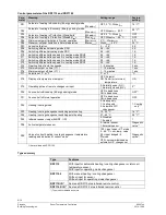
Page 8: ...play of temperature or setpoint OFF Setpoint ON Room or return air temperature ON P19 Operating action of remote changeover input 0 Normally open N O 1 Normally closed N C 0 1 P20 Fan control in Economy Energy saving mode OFF in dead zone ON in dead zone OFF1 P21 Fan control in Normal operation OFF in dead zone ON in dead zone OFF P22 Heating cooling mode 0 Heating only 1 Cooling only 2 Automatic ...

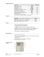
Page 9: ... boxes ARG70 Adapter plate 96 x 120 mm for 2 x 4 conduit boxes ARG70 1 Adapter plate for surface wiring 112 x 130 mm ARG70 2 Ordering When ordering please prodive name and type E g room temperature controller RDF110 The IRA210 infrared remote control is to be ordered as a separate item The QAH11 1 can be used as a return air temperature or automatic heating cooling changeover sensor In case it is ...

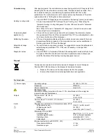
Page 10: ...al conductive paste must be applied to the location on the pipe where the sensor is placed Also refer to the Mounting Instructions B3057 enclosed with the controller Wiring protection and earthing must be installed in compliance with local regulations It must be made certain that safety extra low voltage lines SELV circuit are clearly separated from AC 230 V mains voltage cable The cables to the c...

Page 11: ...point ranges parameters P01 P06 and if necessary to change them accordingly Only with RDF110 Parameters P98 and P99 are diagnostic values and help check the system With P98 the status of the active temperature sensor is shown and with P99 the status of the heating cooling changeover sensor Disposal The devices are considered electronics devices for disposal in term of European Directive 2012 19 EU...

Page 12: ...Setpoints Current temperature value displayed 0 5 C 0 5 C Operation Climatic conditions Temperature Humidity to IEC 60721 3 3 class 3K5 0 50 C 95 r h Transport Climatic conditions Temperature Humidity Mechanical conditions to IEC 60721 3 2 class 2K3 25 60 C 95 r h class 2M2 Storage Climatic conditions Temperature Humidity to IEC 60721 3 1 class 1K3 25 60 C 95 r h EU Conformity CE CE1T3057xx RCM Co...

Page 13: ...y open valves Only with RDF110 or RDF110 IR Connection diagrams Application 2 pipe fan coil units 3057A01 B1 Return air temperature sensor QAH11 1 or external room temperature sensor QAA32 B2 Changeover sensor temperature sensor QAH11 1 changeover mounting kit ARG86 3 M1 3 speed fan N1 Room temperature controller RDF110 S1 External operating mode changeover switch V1 Zone valve Only with RDF110 or...

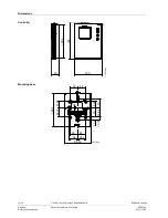
Page 14: ... N3057en Building Technologies 2014 10 28 Dimensions 102 120 3 128 30 3057M02 28 28 35 30 10 15 94 85 28 7 30 4 2 5 21 85 34 15 120 3 31 65 24 35 11 8 28 28 4 3057M03 Controller Mounting base 2006 2014 Siemens Switzerland Ltd Subject to change ...

Reviews: